
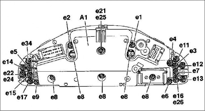
A1. Combined instrument; e1. Signaling device of inclusion of indexes of the left turn; e2. Signaling device of inclusion of indexes of the right turn; e3. Signaling device for turning on the rear light indicators; e4. Signal lamp of the fuel reserve indicator; e5. Battery charge control; e6. Wear control of friction linings of brake pads; e7. Control of the level of brake fluid and parking brake system; e8. Instrument panel lighting; e9. Signal lamp of seat belts; e11. Coolant level control; e12. Oil level control; e13. Control of the water level in the wiper; e14. Monitoring the failure of incandescent lamps; e15. Airbag control; e16. preheating control; e17. Anti-lock braking system monitoring (ABS); e21. Indication of the functioning of the system for regulating the slippage of the drive wheels relative to the supporting surface (ASR); e22. Control of the drive wheel slip control system relative to the supporting surface (ASR); e24. Automatic locking differential control (ASO); e25. Indication of functioning of the automatic blocked differential (ASD); e26. Engine operation control CHECK ENGINE; e34. EDC control
1. Remove the dashboard.
2. If necessary, remove the indicator sockets on the reverse side by turning to the left and replace the bulbs. Mercedes workshops have a special tool for unscrewing the lamp sockets, but this can also be done with fingers or pliers.
3. Replace the lamp only with a lamp of the same wattage and type.
4. Insert the lamp socket and turn it to the right.
5. Mount the dashboard.
Turn signal switch and wiper switch
Removing
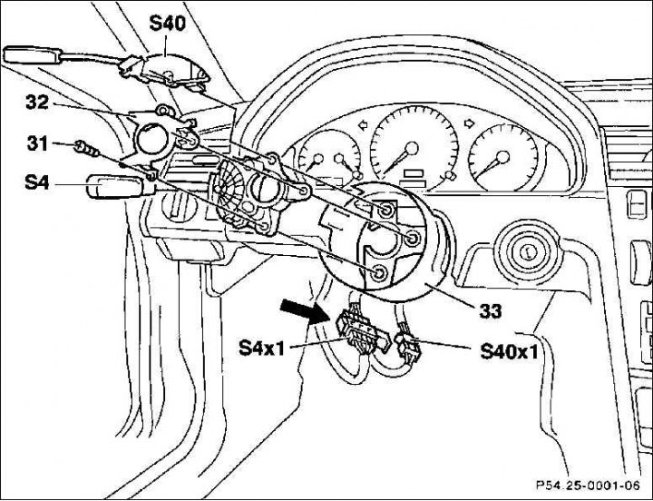
31. Screws; 32. Holder; 33. Casing pipe-shell; S4x1. Plug connector for combination switch; S40x1. Tempomat plug connector; S4. Combined switch; S40. Tempomat switch
1. Remove the protective cover under the instrument panel.
2. Remove the steering wheel.
Attention! Observe the safety precautions when handling the airbag device.
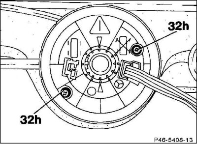
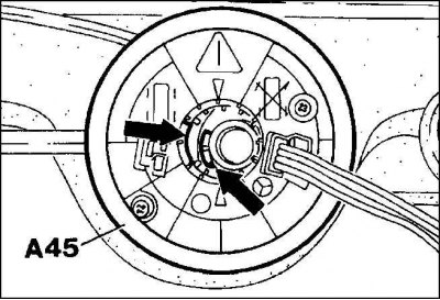
3. Unscrew the screws from the contact coil with the front wheels straight ahead until the contact coil can be removed.
Attention! Do not completely unscrew the screws, otherwise the contact coil will be destroyed and it will need to be set back to the middle position.
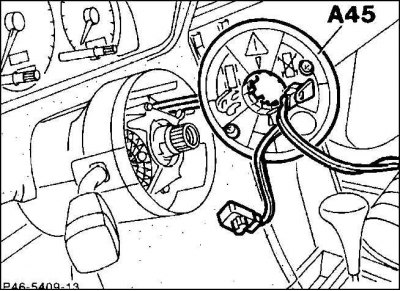
4. Pull the two plug-in connections of the contact coil out of the holder and separate them. Remove the contact coil.
5. Remove the fixing screws to the combination switch.
6. Remove the holder.
7. Remove plug connection (S4x1) and by shifting the byugel (arrow), unlock it.
8. Only when equipped with tempomat: Pull out and separate the plug connection (S40x1).
9. Remove the jacket pipe (33) together with the combination switch, if necessary, also the cruise control switch.
Installation
1. Slide the combination switch together with the jacket tube onto the steering shaft.
2. Push on and screw on the holder.
3. Lay the connecting lines and fix the wire lugs in reverse order.
4. Push the contact coil onto the steering shaft, while laying the connecting wire. Pay attention to the fact that the contact coil is pushed up to the stop and that the groove on the contact spiral coincides with the locking lug on the steering shaft. Tighten the fixing screws tightly. Tie the ends of the wires and fix them.
5. Install the protective cover under the instrument panel.
6. Install the steering wheel.