



Contents: Voltage measurement ↡ Measuring current ↡ Measuring resistance ↡ Installation of additional…↡
Voltage measurement
The presence of voltage can already be proven with a simple test light or voltage indicator. However, in this case it is only determined whether voltage is being applied at all. In order to determine the magnitude of the applied voltage, it is necessary to connect a voltmeter. First of all, when using a voltmeter, it is necessary to set the measurement range in which the measured voltage is presumably located. As a rule, the voltage in a car does not exceed 14 V. The exception is the ignition system: here the secondary voltage of the ignition system can reach up to 30,000 V. This high voltage can only be measured with a special measuring device - an oscilloscope. First of all, the DCV voltage range is set using the selector switch, as opposed to the ACV voltage of alternating current. Then the measurement range is selected. Since the car does not have a voltage higher than 14 volts except for the ignition system, the upper limit of the set measurement range should be set somewhat higher (approximately 15-20 V). If the measured voltage is obviously much lower, for example, it is in the range of two volts, then you can switch to a narrower range to achieve greater accuracy of reading. If higher voltages are applied than determined by the measuring range of the device, then the latter may be damaged.
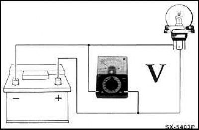
In accordance with the figure, connect the measuring device wires in parallel to the consumer. In this case, the red measuring wire is connected to the wire coming from the positive pole of the storage battery, and the black measuring wire is connected to the wire connecting the storage battery and the car body, or directly to the car ground, for example, to the engine cylinder block.
Example of testing: if the engine does not start properly because the starter rotates too slowly, it is advisable to check the voltage of the battery while pressing the starter. To do this, connect the red wire (+) of the voltmeter to the red terminal of the positive pole of the battery, and the black wire to the vehicle ground (-). Then have an assistant press the starter and read the voltage. If the voltage is below about 10 V (at a battery temperature of +20°C), then it is necessary to check the battery and, possibly, charge it before the next attempts to start the engine.
Measuring current
In a car, it is relatively rare to need to check the current strength. This requires an ammeter, which is also built into the combined measuring device.
Before measuring the current, set the measuring device to the range in which the current to be measured is approximately located. If this is not known, set the highest measuring range and, if there is no indication, successively switch the device to lower ranges.
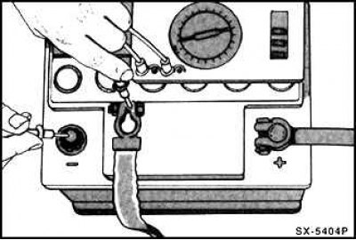
To measure the current, it is necessary to disconnect the electric circuit and connect a measuring device (ammeter) to the break in the circuit. To do this, tighten the plug and connect the red wire (+) of the ammeter to the current-carrying wire. Connect the black wire (-) to the contact to which the broken line is connected. In this case, the ground contacts of the consumer and the plug must be connected using an auxiliary wire.
Warning! Never measure the current with a regular ammeter in the wire going to the starter (about 150 A), or in glow plugs in diesel engines (up to 60 A). The high currents generated can burn out the measuring device. In auto repair shops, an ammeter equipped with a DC clamp is used for such measurements. In this case, the current clamp is clamped over an insulated electrical wire, and the current value is measured using induction.
Measuring resistance
Before measuring resistance, you must be sure that the element of the structure to which the ohmmeter is connected is not under voltage. Therefore, each time, pull off the plug in advance, turn off the ignition, disconnect the wire, for example, from the unit or disconnect the battery. Otherwise, the measuring device may be damaged.
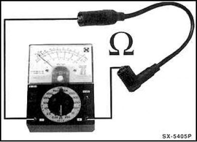
The ohmmeter is connected to two terminals of the consumer (load) or to two ends of the electric line. It does not matter which wire of the measuring device is connected to the terminals.
Resistance measurement in a vehicle is divided into two main areas:
Checking a resistor or structural element built into an electrical circuit.
"Current flow test" in an electrical line, switch or heater coil. This checks whether the electrical circuit in the vehicle is broken and therefore the connected electrical device cannot function. To measure, an ohmmeter is connected to both ends of the corresponding electrical line. If the resistance is 0, then the electrical current flows, i.e. the electrical line is OK. In the case of a broken line, the measuring device shows infinity (in ohms).
Installation of additional electrical accessories
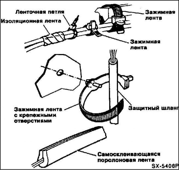
Wires that are to be laid to the installed wiring set in the vehicle when installing accessories should, if possible, always be laid along the individual harnesses using cable ties and rubber bushings. In order to prevent noise while driving and to avoid abrasion of the wires, newly laid wires should be secured using insulating tape, plastic mass, tape clamps for fastening them, etc. In this case, special attention should be paid to maintaining a minimum distance of 10 mm between the brake lines and the rigidly laid wires, and a minimum distance of 25 mm between the brake line and the wires that vibrate together with the engine and other vehicle parts.
When drilling holes in the body, it is necessary to clean, prime and varnish the edges of the holes. The inevitable chips that form during drilling must be completely removed from the body.
When carrying out any installation work that concerns electrical wiring, in order to prevent short circuits in the system, it is imperative to disconnect the battery ground wire (–), which connects its pole to the vehicle body, and hang it to the side.
Caution! If the wires are disconnected from the battery terminals, the fault memory device in the engine and gearbox control system and in the anti-lock braking system, as well as other electrical devices such as the radio and clock, are deactivated under certain conditions, and the accumulated values are erased.
If additional electrical consumers are installed, it should be checked in each case whether the existing three-phase alternating current generator can be additionally loaded. If necessary, it is necessary to provide for the installation of a new generator with a comparatively higher power.