
Instrument cluster
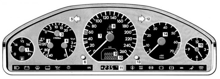
The design of the instrument cluster
1 - Fuel gauge with built-in reserve control lamp; 2 - Coolant temperature gauge; 3 - Current fuel consumption meter; 4 - Engine oil pressure gauge; 5 - Control lamp for activating left turn indicators; 6 - Dashboard illumination intensity control / button for resetting the mileage meter / activating the instrument cluster / switching modes of the active maintenance system (ASSYST); 7 - Speedometer; 8 - Warning control lamp for loss of adhesion to the road systems ASR / ESP; 9 - Screen for displaying current mileage meter readings; 10 - Odometer / active maintenance system / start blocking device indicator screen; 11 - Screen for displaying outdoor thermometer readings; 12 - Control lamp for activating right turn indicators; 13 - Switch for setting the clock / activating the instrument cluster; 14 - Tachometer; 15 - Clock
Instrumentation
Instrument cluster activation
The instrument cluster is activated when the door is opened, by pressing one of the push-button switches mounted in the instrument cluster to the right and left of the speedometer, as well as when the ignition is turned on.
Adjusting the intensity of instrument lighting
Adjusting the intensity of instrument lighting (with running lights on - see Section Access to luggage compartment) is carried out using the turn-and-push handle mounted in the instrument panel on the left under the speedometer dial, - using the same handle, the instrument cluster can be activated and the operating modes of the digital display built into the speedometer can be switched / reset the current mileage counter.
Fuel gauge
The meter is located in the left corner of the instrument cluster and registers the amount of fuel remaining in the tank.
The error in the meter readings is minimal when the car is in a strictly horizontal position. When driving on winding or hilly roads, the error of the instrument increases. The functioning of the meter does not depend on the position of the ignition key. Label 1/1 corresponds to the state of full refueling, 0 - to an empty tank. The control lamp built into the dial of the meter with the image of a filling column notifies the driver of the need to refuel the car as soon as possible.
Combined coolant temperature/current fuel consumption/engine oil pressure meter
The three-function combined meter is located to the right of the speedometer and serves to indicate the value of the engine coolant temperature (bottom left sector), current fuel consumption meter readings (upper sector) and oil pressure sensor readings (lower right sector).
Coolant temperature meter
Under normal conditions, the boiling point of the coolant (antifreeze with added anti-corrosion additives), charged into the system tract designed for operation at overpressure is about 130°C. Under severe operating conditions, such as very hot weather or long uphill climbs, the pointer may rise to the upper red mark on the scale. If the engine temperature has increased so much that the pointer needle enters the red range of the meter scale, you should immediately stop driving, pull over to the side of the road, park and check the condition of the cooling system to determine the causes of engine overheating (see chapter Current service, Troubleshooting).
Current fuel consumption meter
While driving, the meter continuously records the current fuel consumption in l/100 km. In idle and forced idle modes, the meter needle drops to 0.
Driving at very low outside temperatures, in a busy urban cycle (start-stop mode), as well as towing a trailer and driving in mountainous areas are associated with increased fuel consumption.
Engine oil pressure gauge
At operating temperature, oil pressure drops at idle. This does not adversely affect the operational reliability of the engine. Depressing the gas pedal should increase the engine oil pressure.
Speedometer
The speedometer is mounted in the central part of the instrument cluster and shows the speed of the car. The unit of measurement is km/h.
Attention! The sectors of the 30 and 50 km / h ranges highlighted in red serve to track the moments of switching the manual transmission to the next gear.
Tachometer
The tachometer is located to the right of the speedometer and shows the engine speed in thousands of revolutions per minute (arrow reading should be multiplied by 100). In order to avoid engine failure, it is forbidden to exceed the maximum permissible speed of the crankshaft (the tachometer needle should never enter the red zone of the scale).
Attention! In order to protect the engine, when the crankshaft speed reaches the red marking range, the fuel supply is cut off.
Watch
The onboard clock dial is mounted in the right corner of the instrument cluster. The clock setting knob is located on the left under the tachometer dial. Turning the regulator pulled out of the panel clockwise leads to an increase in readings, counter-clockwise to a decrease.
Odometer/Current Odometer/Scheduled Service due indicator display
The display of odometer readings, current mileage counter and scheduled maintenance due date indicator is built into the speedometer dial. Resetting the current mileage counter / switching between the odometer display / scheduled maintenance indicator is done using the push button switch located on the left under the speedometer dial.
Current mileage counter
The meter records the current mileage of the vehicle since the last time it was reset (in kilometers or miles, depending on the version). The meter readings are displayed in the upper field of the digital indicator built into the dial of the speedometer. To reset the meter, activate the instrument cluster, then press the reset button and hold it down for about 1 second.
Odometer
The odometer records the total mileage of the vehicle in kilometers since the start of operation. The odometer readings are displayed in the lower field of the digital indicator mounted in the speedometer dial.
Scheduled maintenance due date indicator (active maintenance system - Assyst)
Attention! See also Section Vehicle identification numbers Chapters Current service
The scheduled maintenance due date indicator informs about the OPTIMAL maintenance period and its readings are not related to the level of engine oil.
Attention! If the battery is disconnected, then the parking time of the car is not included in the countdown of the scheduled maintenance period - to maintain the frequency of routine maintenance procedures, this period of time must be taken into account.
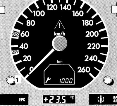
Information about the timing of scheduled maintenance is displayed in the field of odometer readings built into the digital display dial of the speedometer
1 - Button to switch the display to odometer mode
Approximately one month before the due date of the next maintenance, with the ignition on, the value of the remaining mileage or time is displayed in the odometer field of the digital display of the speedometer (in days) until the next maintenance procedure is performed.
At the same time, the reading
Switching the display to the odometer mode occurs automatically after 10 seconds, or by pressing the button (1).
If the maintenance period is overdue, the indicator starts to work in a flashing mode, in addition, a minus sign is displayed in front of the digital data.
It is also possible to output service readings manually, for which you must first activate the instrument cluster, and then press the button twice within 1 second (1). Switching the display to the odometer mode, as before, occurs automatically after 10 seconds, or by pressing the same button.
Scheduled maintenance due date indicator switches off automatically after 10 s or goes out when the button is pressed (1).
The indicator is reset at a Mercedes-Benz workshop where scheduled maintenance was performed.
If necessary, the indicator can be reset on its own by the car owner:
- Turn the ignition key to position 2 and immediately press the button twice within 1 second (1).
- The last indication of the due date of the scheduled maintenance is displayed in the counter of the total distance traveled.
- Turn the key in the steering wheel lock to position 0 for approximately 10 seconds.
- Click the button (1) and keep pressed.
- Turn the ignition key to position 2.
- button (1) continue to hold down, the display screen will remain illuminated indication of the old period of the previous service, then, approximately 10 seconds after the beep, the period of the next maintenance will be displayed, - release the button (1).
- If the due date display is accidentally reset, the function can be reactivated at a Mercedes-Benz workshop.
- The amount of mileage remaining until the next maintenance is performed is determined by the driving style and ranges from 15,000 to 22,500 km (365÷730 days). An economical driving style at medium engine speeds and the refusal to travel short distances contribute to its increase.
Schedule of ongoing maintenance car is presented in Chapter Current service.
Control lamps and indicator lights
A whole complex of control lamps and indicators is built into the assembly of the car's instrument cluster, with the help of which the driver receives important information about the serviceability / violation of the functioning of the main units and systems of the car. Below, the reader is offered information on the principle of operation of each of the provided light indicators separately.
List of control lamps and indicator lights included in the instrument cluster
EPC Control lamp of refusals of electronic control system of injection of the diesel engine.
BAS
ASR Control lamp of failures of the BAS/ASR systems.
BAS
ESP Control lamp of failures of the BAS/ESP systems.
ABS Control lamp of refusals of ABS.
SRS Control lamp of failures of elements of system of additional safety (SRS).
This warning lamp comes on briefly when the ignition is switched on and should go out as soon as the engine is started. The activation of this warning lamp is accompanied by a forced shutdown of the anti-slip (ASR) and anti-skid (ESP) systems (see Sections Anti-slip system (ASR) and Electronic anti-skid system (ESP)). Activating the flashing light while the vehicle is moving alerts the driver that the vehicle's wheels are at the limit of traction and must slow down to a safe level.
This light indicator lights up simultaneously with the inclusion of the high beam of the headlights of the car and has a characteristic blue glow.
The charge control lamp should light up when the ignition is switched on and go out immediately after starting the engine. Turning on this warning lamp with the engine running warns the driver about a malfunction in the charging system, i.e., the battery goes into discharge mode. You should immediately turn off all consumers of electricity, the operation of which does not affect road safety and try not to stop the engine, as an attempt to start it can lead to the final discharge of the battery. Check the condition and tension of the alternator drive belt, if necessary, make appropriate adjustments. If the belt is in order, the vehicle should be immediately driven to the nearest service station to diagnose the failure and perform the necessary remedial repairs.
This warning lamp comes on briefly when the ignition is switched on and should go out as soon as the engine is started. The activation of the warning light while driving indicates that the washer fluid level has fallen to approximately 1/4 of the volume of the respective reservoir.
This warning lamp comes on briefly when the ignition is switched on and should go out as soon as the engine is started. The activation of the warning lamp while driving indicates that the coolant level in the expansion tank has dropped to a dangerous limit and an appropriate adjustment must be urgently made.
Engine oil pressure warning lamp (red) should light up when the ignition is turned on and go out immediately after starting the engine. The flashing of the lamp with the engine running indicates a pulsating decrease in the working pressure of the engine oil in the engine. When the light stays on, it indicates that the oil pressure has dropped to a dangerously low level, which is fraught with serious internal engine damage, up to and including its complete failure. In both cases, urgent action should be taken to correct the oil level, identify and eliminate the causes of pressure drop.
This warning lamp comes on briefly in a dim mode when the ignition is switched on and should go out as soon as the engine is started. Activating the lamp in bright light mode (both when the ignition key is turned to position 2 and while driving) indicates the failure of the incandescent lamp of one of the external lighting / signaling devices.
Attention! If the stop lamp fails, the warning lamp will only come on during braking.
Attention! Any additional lighting fixtures must be connected through a fuse installed in front of the incandescent lamp control unit. A neglectful attitude to the fulfillment of this condition is fraught with failure of the control lamp, lighting fixtures and the control unit.
EPC Control lamp of refusals of electronic control system of injection of the diesel engine
Activation of this warning lamp when the engine is not running warns the driver of a malfunction in the fuel management system. The power developed by the engine in such a situation can be noticeably reduced and the car should be driven to the nearest Mercedes-Benz workshop.
The control lamp is briefly activated in a weak glow mode when the ignition is switched on and should go out immediately after the engine is started. Failure of the lamp to turn off, as well as its activation while driving, indicates a malfunction of the automatic damping system that controls the stiffness of the car's suspension shock absorbers, depending on the condition of the road, load and driving style. The car should be taken to a Mercedes-Benz workshop as soon as possible.
Attention! When the on-board power is turned off due to disconnection or discharge of the battery, the control lamp will light up with the engine running. Turn the steering wheel from lock to lock to turn off the lamp.
BAS
ASR Control lamp of failures of the amplifier of emergency braking (BAS) / traction control (ASR)
The control lamp is briefly activated when the ignition is switched on and should go out immediately after the engine is started. Failure of the lamp to turn off, as well as its activation while driving, indicates a malfunction of the BAS or ASR system.
Attention! If the BAS system fails, the vehicle's braking system continues to function normally (unenhanced) mode.
A malfunction of the ASR system can lead to a noticeable reduction in the power developed by the engine. The vehicle should be taken to a Mercedes-Benz workshop without delay for diagnosis and necessary repairs.
BAS
ESP Control lamp of failures of the amplifier of emergency braking (BAS) / anti-skid system (ESP)
The control lamp is briefly activated when the ignition is switched on and should go out immediately after the engine is started. Failure of the lamp to turn off, as well as its activation while driving, indicates a malfunction of the BAS or ESP system.
Attention! If the BAS system fails, the vehicle's braking system continues to function normally (unenhanced) mode. Note: Malfunction of the ESP system can lead to a noticeable reduction in the power developed by the engine. The vehicle should be taken to a Mercedes-Benz workshop without delay for diagnosis and necessary repairs.
This warning lamp is used to monitor the correct functioning of the ABS, it works briefly when the ignition is turned on and should go out a few seconds after the engine is started.
The control lamp is briefly activated when the ignition is switched on and should go out immediately after the engine is started. Activation of the lamp during braking indicates wear of the friction linings of the brake pads to the maximum permissible value and the need for urgent replacement.
Pilot lamp (red) lights up continuously when the parking brake is applied, reminding the driver to release it before starting to move. Driving with the parking brake applied leads to rapid overheating and failure of the brake mechanisms of the rear wheels of the car, as well as to premature wear of the rear wheel tire treads, and in addition, it can cause a malfunction of the anti-lock brake system (ABS).
If the warning light stays on after the parking brake is released, or if it comes on while driving, this usually indicates an excessive drop in the brake fluid level. One of the possible reasons for the gradual decrease in the level of brake fluid is the normal wear of the friction linings of the brake pads. When the warning lamp comes on, the car should be driven to the nearest service station to assess the condition of the pads and check the tightness of the hydraulic path of the brake system.
A short-term operation of the control lamp also occurs when the ignition is switched on (even with the parking brake released).
SRS Control lamp of failures of elements of system of additional safety (SRS)
This warning lamp comes on for approximately 4 seconds when the ignition is switched on and should go out as soon as the engine is started. If the lamp continues to burn while the engine is running (in continuous or flashing mode), this indicates a malfunction of the SRS system components. If equipped, the operation of this warning lamp may indicate a malfunction in the circuits of the side and head airbags, or the devices of the automatic emergency seat belt tensioners.
This indicator has an amber glow and briefly works when the ignition is turned on. The indicator's transition to flashing mode after the engine is started is intended to remind the driver/passengers to fasten their seat belts.
The preheating indicator lamp lights up when the ignition is switched on and indicates that the preheating system has been activated. The engine must not be started before the warning lamp turns off.
Direction indicator lights
Light indicators in the form of arrows have a green glow and serve to monitor the proper functioning of the corresponding direction indicators. The direction of the indicator arrows coincides with the selected direction of change of the vehicle's course. The indicators work in a flashing mode with a frequency corresponding to the frequency of blinking of the direction indicators. The rapid blinking of one of the indicators usually indicates a burnout of the lamp of one of the indicators of the corresponding turn. It is necessary to replace the burned-out lamp as soon as possible so as not to create emergency situations on the roads.
Simultaneous flashing of the indicator lights of both directions is usually accompanied by the activation of the alarm.