



Contents: General information ↡ General notes on the operation of…↡ Governing bodies ↡ Control panel for the functioning of…↡
General information
The automatic air conditioning system, which is standard on all models, only operates when the engine is running. When the economy mode (EC) is selected, the cooling system does not operate.
The transition to the selected temperature mode is always carried out at the maximum possible speed.
Note: Minor temperature fluctuations around the set point are due to solar radiation and changes in outside air temperature.
The design of the system allows maintaining an individual microclimate on both sides of the cabin.
Note: The temperature change step should not be too large.
A plug-in filter built into the intake tract protects the interior from dust and plant pollen.
General notes on the operation of the K/V system
The operation of the air conditioning system may result in condensation forming under the bottom of the vehicle; a small puddle forming under a parked vehicle in hot weather should not cause concern.
In hot sunny weather, before starting to drive, you should ventilate the sun-heated interior of the car.
Make sure that the air vents in the space between the rear shelf and the rear window of the vehicle remain open.
In winter, clear snow from the air intake grille in front of the car's windshield before driving.
In case of refrigerant leaks, the operation of the air conditioning system is automatically suspended and the system switches to economy mode.
Governing bodies
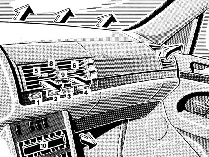
Air flow distribution diagram and front air duct output control elements
1 - Left side nozzle flow area regulator; 2 - Left central nozzle flow area regulator; 3 - Right central nozzle flow area regulator; 4 - Right side nozzle flow area regulator; 5 - Left central nozzle deflector; 6 - Right central nozzle deflector; 7 - Side nozzle deflector; 8 - Output flow heating on/off button; 9 - Output flow cooling on/off button; 10 - Control panel K/V with digital information display
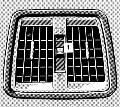
Rear air duct nozzle deflector (models without rear air conditioning)
1 — Nozzle flow area regulator

Rear air duct nozzle deflectors (models with rear air conditioning)
1 - Temperature regulator on the left side of the rear compartment
2 - Temperature regulator on the right side of the rear compartment
3 — Nozzle flow area regulator
4 — Left nozzle deflector
5 — Right nozzle deflector
6 — Regulator of the mixing flap of the air flow distribution directions (through nozzles/into foot wells)
Air is supplied to the vehicle's interior through a network of ventilation ducts ending in nozzles equipped with deflectors.
Air is supplied to the front of the cabin in four main directions: to the front level of the driver and front passenger (central and side instrument panel deflectors), for windshield blowing (front instrument panel deflectors), for blowing side windows (side deflectors) and into the foot wells (lower air ducts).
The front air duct outlets are located on the instrument panel and in the passenger compartment footwells.
The design of the louvered deflectors of the outlet nozzles of the front level air ducts allows you to control the intensity (complete closing of the nozzle is achieved by turning the regulator all the way to the right) and direction (the nozzle assembly is pivotal) outgoing flows. Two push-button switches built in between the central deflectors allow you to turn on/off the autonomous heating/cooling of the outgoing flow.
Note: In basic mode, all buttons are released.
The deflectors of the air supply nozzles to the rear of the passenger compartment can have one of two designs, depending on whether the air conditioning mode is provided here or not.
The A/C control panel with integrated digital information display is located in the upper part of the front section of the centre console.
Control panel for the functioning of the automated K/V system
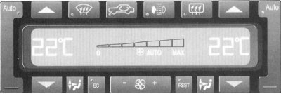
Design of the control panel of the air conditioning system
 — AUTO mode activation buttons
 — Buttons for increasing the maintained temperature value
 — Buttons for decreasing the maintained temperature value
 — Button for turning on the condensation removal/window defrosting mode
Original can be found on the website MercedesMAN
 — Air circulation mode switching button
 — Button for connecting the cabin filter to the air inlet duct of the air conditioning system
 — Rear window heating switch
 — Air flow distribution buttons
 — Economy mode on/off button
 — Key switch for forced selection of fan speed mode
 — Button for turning on the engine residual heat mode
Automatic operation mode
The automatic system operation mode is basic. To activate the mode, press the buttons simultaneously

in the upper corners of the control panel, - the LEDs built into the buttons should light up. To set a comfortable room temperature (22°C) in the cabin, press the buttons simultaneously
 and
and  . The following information will be displayed on the display screen:
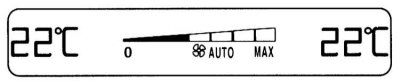
The air flow intensity and distribution in this mode will be adjusted automatically. The temperature mode selection buttons on the central air vents of the instrument panel must be pressed.
Glass defrosting mode
Fully open the side glass openings of the instrument panel.
To activate the glass defrosting mode, press the button
 , - the control LED built into the button should light up. The following information will be displayed on the screen:
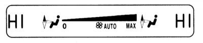
To turn off the glass defrosting mode, press the same button again.
Glass condensation removal mode
To quickly remove condensation from the glass, turn off the economy mode
 or closed circulation mode
  , then activate the automatic mode by pressing the buttons simultaneously
  (the control LEDs should light up) and using the buttons
  manually select the air supply mode to the upper part of the cabin. The following information will be displayed on the display screen:

Do not forget to fully open the flow sections of the side nozzles of the instrument panel.
Economy mode
To activate the economical mode, press the EC button - the control LED built into the button should light up.
In economy mode, system functions such as cooling and dehumidification are disabled.
The mode is disabled by pressing the same button again.
Forced selection of air flow distribution direction
The direction of air flow distribution is selected using the buttons
 control panel. Press the buttons until the display screen confirms the required switching. In the example below, the air supply mode for blowing air to the driver's side of the car and to the front passenger's feet is selected:
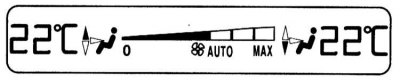
To activate the air supply through the central nozzles of the instrument panel, press one of the deflectors buttons.
Return to automatic mode by pressing the AUTO buttons.
Forced selection of air supply intensity
The fan can be operated manually at one of seven speed settings using a key switch
 , - supporting information is displayed in graphic form on the display screen (darkening of wedge indicator sections):
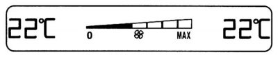
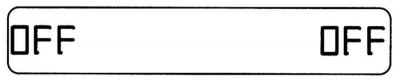
The same switch is used to turn off the air conditioning. Continue pressing the switch until the display screen shows the message "OFF" and the air supply to the passenger compartment stops:
Note: Turning off the air conditioning system for a long period of time may cause the windows to fog up.
Activation of K/V can be done by pressing one of the buttons
 or
or  , or by pressing the "+" section of the key switch
  .
.
Engine residual heat utilization mode
The interior can be heated for some time after the engine has stopped by using residual heat. The corresponding mode is activated using the button
 on the control panel, the control LED built into the button should light up.
Before turning on the mode
 turn the ignition key to position 0 or 1, or remove it from the lock. Also, close the flow section of the nozzle/nozzles of the rear air duct.
In mode
 the intensity and direction of air supply are adjusted automatically.
Note: A prerequisite for using the mode is
The mode is switched off automatically by a timer signal after approximately 30 minutes, when the ignition key is turned to position 2, and also when the battery charge level noticeably decreases.
Air circulation mode
The air circulation mode is activated using the button
 control panel K/V, - the control LED built into the button should light up. In this mode, the supply of fresh air to the passenger compartment is turned off. This function allows you to prevent polluted or foul-smelling air from entering the car.
Note. Long-term use of closed circulation leads to fogging of the windows and increased air tightness, so it is recommended to turn on this mode only if necessary and for a relatively short time, for example, when driving in an area with a smoky or polluted atmosphere. As soon as the need for interior insulation disappears, the supply of fresh air should be resumed.
Pressing the switch button again restores the air supply.
There is also an automatic shutdown of the closed circulation mode according to a timer signal: approximately after 30 minutes at outside air temperatures above +5°C, after 5 minutes at temperatures below 5°C and after 5 minutes in the economical (EC) mode of the air conditioning system.
Note: At high outside temperatures, the closed-circulation mode is activated automatically - a portion of fresh air will be supplied to the passenger compartment approximately every 30 minutes. In addition, a dangerous increase in the concentration of carbon monoxide (CO) or nitrogen oxides (NOX) in the inlet stream leads to automatic activation of the closed-circulation mode, provided that the mode is disabled EC and the outside air temperature is not lower than +7°C.
Connecting the cabin filter to the air intake tract
When you press the button
 the cabin filter filled with activated carbon is connected to the air intake tract of the air conditioning system on the control panel of the air conditioning system. The activation of the filter is confirmed by the operation of the control LED built into the switch button.
Connecting a cabin filter allows you to sharply limit the concentration of harmful components in the intake air flow and prevent unpleasant odors from entering the car's interior.
In order to maintain the set air supply intensity, when the filter is connected, the fan speed of the air conditioner is automatically increased.
Note: An increase in the concentration of carbon monoxide (CO) or nitrogen oxides (NOX) in the outside air leads to automatic activation of the closed circulation mode (see above).
Activating modes
 and defrosting of glass (
 ) leads to automatic shutdown of the cabin filter.
If you need to quickly warm up/cool down the interior, the filter should also be turned off.
Rear window heating
The rear window heating only functions in position 2 of the ignition key. The rear window heating element is activated using the button
 on the control panel of the air conditioning system (see illustration 19.3), - the control LED built into the button should light up.
Note: In winter, remove ice and snow from the glass before turning on the heating.
Note: The rear window defroster heating element consumes a lot of electricity, so do not activate it for a long time.
The heating is automatically switched off by a timer signal after approximately 12 minutes.
Note: The rear window heating may also be switched off if a large number of power consumers are activated at the same time, or if the battery charge level drops significantly - the built-in button