
Switches located on the steering column
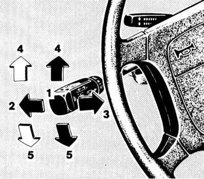
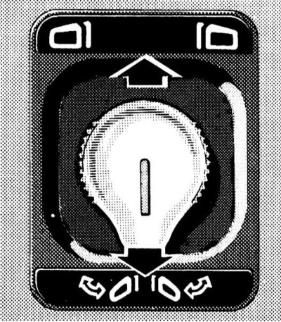
Combination switch
Switching the operating modes of the headlights (near/far light) and activation of direction indicators
Switching the operating modes of the headlights and activating the direction indicators
1 - Position «dipped beam»
2 - Position «high beam»
3 - High beam signaling
4 - Activation of right turn indicators
5 - Activation of left turn indicators
The headlights are switched from the low beam mode to the high beam mode by pushing the steering column switch lever away from you - the corresponding control lamp of the characteristic blue light should automatically light up on the instrument panel. To turn off the high beam, return the lever to its original position.
The possibility of high beam signaling is also provided: the signaling is carried out by pulling the stalk lever towards you and regardless of the selected position of the handle for selecting the mode of operation of the external lighting devices.
Note. High beam signaling remains possible even when the ignition is switched off.
The direction indicators are activated by pushing the left stalk lever in the corresponding direction (black arrows). The lever is moved up or down, depending on the selected direction of change of course.
When moving the lever to the extreme upper/lower position (click) the corresponding direction indicators will continue to function until the steering wheel is returned to the straight-ahead position (the limit switch will work), or until the lever is returned to neutral.
Short-term inclusion of indicators, for example, when intending to change the lane of movement, is done by slightly pulling the lever up or down (white arrows).
Windshield wipers/washers and headlight lens controls
Note. The washer fluid reservoir, as well as the lines and nozzles for its supply, are equipped with heating elements.
Activation of windshield wipers and washers and headlight lenses is only possible with the ignition on (key in the ON or ACC position).
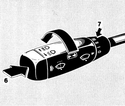
Windshield wipers/washers and headlight lens controls
6 - Push-button switch for washer fluid supply
7 — the Ring switch of a choice of a mode of functioning of a screen wiper
Briefly pressing the end button switch causes a single operation of the windshield wiper without washer fluid.
Note. The mode should only be used when the windshield is wet.
Depressing the pushbutton switch against resistance allows the washer fluid to be applied to the windshield, accompanied by the operation of the wiper. When the navigation lights/dipped beam are on, the headlamp cleaners will be activated at the same time.
Activation of regular wiper modes is carried out using a ring regulator installed at the rear of the combination switch handle. In position 0, the wipers are off. Switching the regulator to position I leads to the activation of the wipers in the interval mode.
Note. On models equipped with a rain sensor, the windshield wipers make one stroke, then the period of the wipe cycles is automatically adjusted. In position II, the wipers operate at normal speed. Position III is used to switch the windshield wipers to the accelerated operation mode.
Note. On models equipped with a rain sensor, when the vehicle is stopped, the wiper period is automatically switched back one step.
Steering column switch for controlling the operation of the tempostat
The tempostat function control switch is located on the steering column above the combined steering column switch.
A detailed description of the principles of controlling the functioning of the tempostat is given in Section Speed control systems (tempostat) and Speedtronic.
Horn activation button
The horn button is built into the hub of the steering wheel.
Switches and controls located on the instrument panel and front section of the center console
Selecting the mode of operation of external lighting devices (dimensions, light) is carried out using the rotary handle located on the left side of the instrument panel.
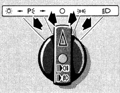
It is possible to select one of the following outdoor lighting modes.
ABOUT Turned off.
The standard equipment of all models includes the function of sound notification of the driver about the need to turn off the lights before leaving the car. The alarm buzzer sounds when you try to open the driver's door with the ignition off (key in position 0 or 1) in case the outdoor lighting mode selection knob is not moved to position 0 or one of the parking positions
Note. Remember that excessively long operation of outdoor lighting with the engine turned off is fraught with a battery drain!
Headlight beam tilt adjuster
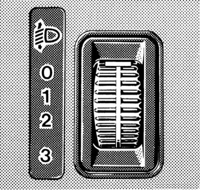
The wheel switch for adjusting the tilt of the optical axes of the headlights is located on the left side of the instrument panel and has four fixed positions (0, 1, 2 and 3)
The switch serves to adjust the lighting distance (when turning on the low beam), in order to prevent blinding of drivers of oncoming and ahead vehicles.
The regulator must be set to (according to the tables below), corresponding to the number of passengers and the degree of vehicle loading.
Models with adjustable ride height
| Switch position | Number of people in the front seats | Number of people in the rear seats | Cargo in the luggage compartment |
0 | 1 or 2 | 0 | Absent |
1 | 1 | 3 | Full load |
2 | 2 | 3 | Full load |
3 | Not used | ||
Models without ride height adjustment
| Switch position | Number of people in the front seats | Number of people in the rear seats | Cargo in the luggage compartment |
0 | 1 or 2 | 0-3 | Doesn't matter |
1 | 1 | 0 | Full load |
2 | Not used | ||
3 | Not used | ||
Parking brake release handle
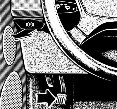
The models covered in this manual use a foot operated parking brake. The parking brake is applied by depressing the pedal located on the left under the instrument panel. The parking brake release handle is on the left of the vehicle's instrument panel and is marked with a pictogram of the corresponding content. Pulling the handle causes the parking brake to be released instantly, - the corresponding indicator lamp (see Section Instrument cluster, meters and control lamps and indicator lights) on the instrument panel should go out.
Steering wheel adjustment
Manual Regulator Models
The lock release lever is located on the left side of the instrument panel. To release the latch, press the lever down to the stop, then pull the steering wheel towards you, or push it away from you. Having achieved a comfortable position of the steering wheel, press the lever down and release - the return of the lever to normal (locked) position should happen automatically.
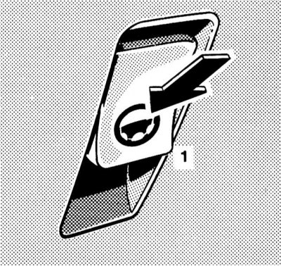
Electric Governor Models
The power steering operation control switch is located on the left side of the instrument panel. The power steering column operates only when the ignition is on.
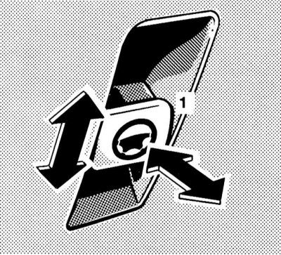
To adjust the position of the steering wheel in the longitudinal direction, pull the switch (1) towards you or press it into the instrument panel. The position of the column in the vertical plane is adjusted by moving the switch lever in the appropriate direction.
The selected steering column/wheel position can be stored in the on-board processor along with the seat and door mirror positions (see Section Seat adjustment).
Ignition switch/steering column lock
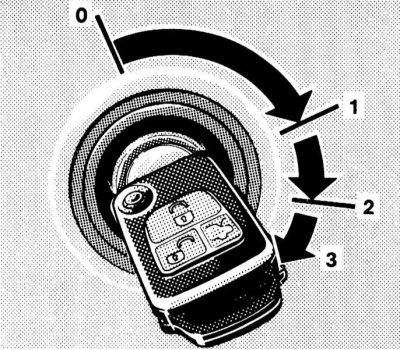
The ignition switch is located on the instrument panel to the right of the steering column. The key can occupy one of four fixed positions in the lock:
- 0 - Steering column lock
- 1 - Auxiliary consumers of electricity (parking position)
- 2 - Ignition on
- 3 - Engine start
Position 0 - steering column lock
The key can only be entered or removed from the lock in this position. Turning the ignition key from position 0 to position 1 unlocks the steering column. In addition, on models equipped with an automatic transmission, an additional condition for starting permission is the mandatory transfer of the selector lever to the position «R».
The key can only be removed from the ignition switch after turning it to position 0.
Note. On models with AT, removing the key from the ignition lock becomes possible only after moving the selector lever to the position «R».
The steering column is locked automatically when you try to turn the steering wheel after removing the key from the ignition.
The steering column lock sometimes results in the inability to turn the key in the ignition. In such a situation, turn the steering wheel slightly in one direction or another (in order to relieve the burden), while turning the key in the lock.
Note. Never remove the key from the ignition lock while driving! This will inevitably lead to steering column lock and loss of control. Remove the key from the lock only after the vehicle has come to a complete stop!
Note. With the front door open, it remains possible to activate the electric seat adjustment, steering column, power windows and sunroof cover with the key removed from the ignition switch.
Position 1 - parking
In this position of the ignition key, the auxiliary consumers of electricity can operate (audio system, cigarette lighter, heater fan, windshield wipers, etc.).
Position 2 - ignition on
In this position, the ignition key is constantly while the car is moving, as well as when the engine is idling. On diesel models, turning the key to position 2 before starting the engine activates the preheating system. At the same time, electrical power is provided to all systems and additional equipment installed on the vehicle. When the key is turned from position 1 to position 2, some of the control lamps located on the dashboard of the car briefly turn on, confirming the correct functioning of the corresponding control systems (see Section Instrument cluster, meters and control lamps and indicator lights).
Position 3 - start
Turning the key to this position engages the starter. After starting the engine, the key must be released and it will automatically return to the «ON».
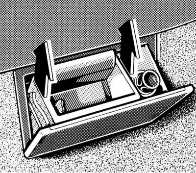
Latch release buttons and lock for glove box and glasses compartment
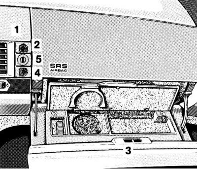
Buttons for opening and locking the lids of the glove box and glasses compartment
1 - Compartment for glasses
2 - Button for releasing the latch of the lock of the glasses compartment
3 - glove box
4 — The button of a release of a latch of the lock of a ware box
5 — The lock of covers of a ware box and office for points
The buttons for releasing the locking latches of the glove box and the glasses compartment are located in the central part of the instrument panel, to the right of the deflector panel.
With the help of the upper of the two buttons, the latch of the lock of the glasses compartment is released, the lower one - of the glove box, between the buttons is placed the lock cylinder for locking both covers. Both covers are locked simultaneously by turning the key in the lock cylinder to the right and then removing it.
Note. On models equipped with a trip computer, there is a display assembly in place of the glasses compartment, the hinged cover of which is raised using the top button.
Trunk lid latch release button
The remote release button for the trunk lid latch is located on the left side of the top row of switches in the center console.
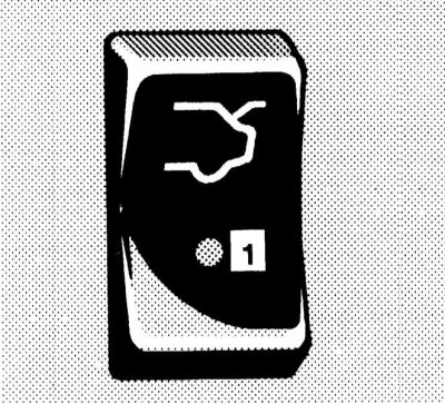
To release the latch, press the button - the built-in control LED should be activated.
Note. After releasing the latch, the luggage compartment lid folds up, so make sure that there is adequate free space!
Tow/Intrusion Prevention Disable Switch/Theft Alarm Control LED

Switch for disabling protection devices against unauthorized entry into the passenger compartment / towing a car
1 - Disable the towing protection device
2 - Control LED
3 - Disabling the protection device against unauthorized entry into the passenger compartment
With the appropriate vehicle equipment, the activation of the devices in question occurs automatically when the doors are locked / the anti-theft alarm is activated.
Note. There is a delay of approximately 60 seconds for the volume sensors of the anti-intrusion device to activate.
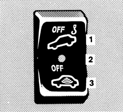
The corresponding device activation switch is located second from the left in the top row of switches in the center console and is equipped with a built-in anti-theft alarm control LED, which is activated approximately 15 seconds after the doors are locked - the LED begins to flash steadily.
Deactivation of the corresponding protective system is carried out by pressing the corresponding section of the switch key after removing the key from the ignition lock - the built-in control LED should light up briefly, then go out, confirming the deactivation. Further, the car can be locked and the anti-theft alarm can be activated from the remote control (see Single lock). The corresponding device remains disabled until the car is locked again with the remote control.
Switch for releasing the latches/controlling the function of the electric drive for adjusting the position of the rear seat headrests
Models with manual rear headrest adjustment
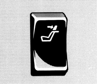
With this configuration, the release of the rear seat head restraint latches is carried out remotely using the middle key switch in the top row of console switches. The drive can only be activated when the ignition is on. To release the latches, press the top of the button, then manually adjust the headrests (see Seat adjustment).
Models with electric rear head restraint adjustment
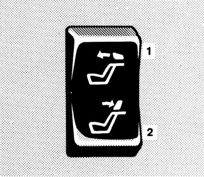
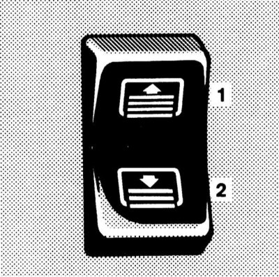
The switch of management of functioning of the electric drive of adjustment of back head restraints
1 - Raise the head restraints
2 - Lower the head restraints
The power rear head restraint operation control switch is located in the middle of the upper row of console switches. The drive can only be activated when the ignition is on.
Note. Additional switches for adjusting the height of the head restraints are individually mounted in the armrests of the rear doors of the car, while the tilt of the head restraints is set manually.
Adjustment of the position of the head restraints is carried out by pressing the corresponding part of the switch button.
Single Lock Actuator Switch / Anti-theft Alarm Control LED
Single lock drive switch
1 - Locking locks
2 - Unlocking locks
The single lock drive switch is located second from the right in the top row of console switches.
Pressing the upper section of the switch locks the locks, pressing the lower section unlocks.
On models not equipped with an intrusion/tow protection system, the anti-theft alarm warning lamp is also built into the button of this switch, which is activated approximately 15 seconds after the doors are locked - the LED begins to flash steadily.
Note. The anti-theft alarm is deactivated automatically when the car doors are unlocked by any of the standard methods (see doors).
Hazard switch
The alarm is activated using the rightmost button in the top row of console switches. The switch button is equipped as standard with a signal lamp with a pictogram depicting two triangles inscribed in each other.
Turning on the alarm leads to the simultaneous operation of all four direction indicators (and their indicator lights on the vehicle dashboard). The alarm system is designed to warn other road users about the forced stop of the car and is also used in other dangerous situations provided for by traffic rules.
Keys for disabling anti-slip control (ASR) and anti-skid (ESP) systems
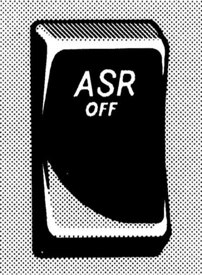 | 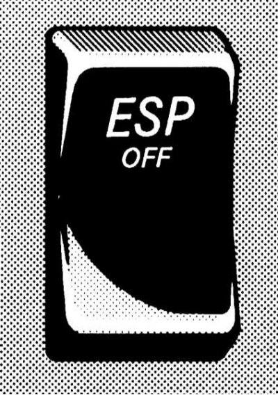 |
Keys for disabling ASR and ESP functions (see Sections Anti-slip system (ASR) and Electronic anti-skid system (ESP)) are placed at the top left in the second from the top section of the center console, to the left of the ashtray.
The shutdown of the systems is accompanied by the activation of the warning indicator lamp built into the dial of the speedometer (see Section Instrument cluster, meters and control lamps and indicator lights).
Disabling is done by pressing the upper part of the key of the corresponding switch.
Automatic damping system mode switch (ADS)
The switch is located in the upper right corner of the second section of the center console from the top, to the right of the ashtray, and allows you to switch the operating modes of the ADS system, which controls the stiffness of the suspension.
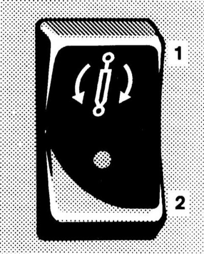
The switch of modes of functioning of an automatic damping system of a suspension bracket (ADS)
1 - Sport driving mode
2 - Comfort mode
When the sport driving mode is activated, the control LED integrated in the switch button lights up.
Seat heating switches
Two seat heating key switches are located on both sides of the front ashtray, in the lower corners of the second section of the center console from the top, and allow you to activate two seat heating modes (normal and fast), and turn off the heaters.
The heating of the front seats is activated in positions 1 and 2 of the ignition key, the rear seats - only in position 2.
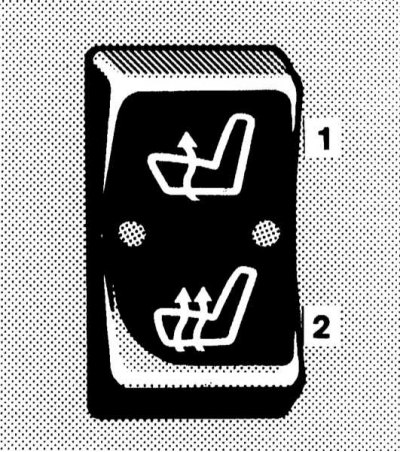
Seat heating switch
1 - Normal heating
2 - Accelerated heating
Activation of the normal mode is accompanied by the operation of one of the two control LEDs built into the switch. During accelerated heating, both LEDs light up.
The heating is turned off as follows: if one built-in control LED is on, press the upper part of the button of the corresponding switch, two - the lower one. The automatic shutdown of the heating elements occurs at the timer signal after approximately 30 minutes of continuous operation of the heating elements.
Note. The seat heating is also switched off when the charging system is overloaded or the battery charge level is insufficient - in this situation, one or both control diodes (depending on the selected heating mode) switch to flash mode. After removing overload (disconnection of excess electricity consumers) the seat heating will be activated automatically.
The switch of management of functioning of the electric drive of external rear-view mirrors
The switch is located in the upper left corner of the third section from the top of the center console, to the left of the selector lever (AT) /shift knobs (RKPP).
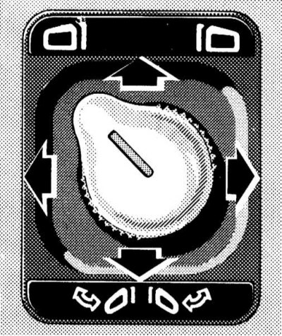
Driver's Door Mirror Adjustment Mode
Mirror folding/unfolding mode
The switch has a joystick design and is equipped with a rotary handle, with which you can select the mirror to be adjusted, as well as select the operating modes of the electric drive (adjustment/folding).

To switch to the mirror adjustment mode, turn the rotary knob with the nose in the direction of the corresponding icon, then carry out the actual adjustment by moving the joystick in the appropriate direction
To fold the mirrors during parking or before washing the car, turn the rotary handle with the nose down and press the joystick down - both mirrors will press against the windows of their doors. The mirrors are deployed by pushing the joystick up.
Note. Turn the mirrors all the way to avoid vibration while driving. The selected position of the exterior mirrors can be stored in the on-board processor along with the steering column/wheel and seat positions (see Section Seat adjustment).
Main switches for controlling the operation of the electric power window drive
Four individual switches for controlling the operation of the electric door windows are located on the center console to the right and left of the selector lever assembly (AT) /shift knobs (RKPP).
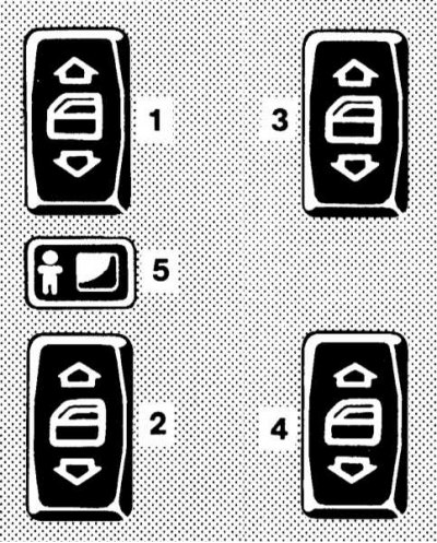
Main switches for controlling the operation of the electric power window drive
1 — The switch of activation of the regulator of a window regulator of a driver's door
2 — The switch of activation of a regulator of a window regulator of the right forward door
3 — The switch of activation of the regulator of a window regulator of the left back door
4 — the Switch of activation of a regulator of a window regulator of the right back door
5 - Button for blocking the activation of rear window regulators from individual door switches
Each switch allows you to activate the power window regulator drive of the corresponding door. The slider located between the left door switches allows, if necessary, blocking the possibility of activating the rear door window regulators from individual door switches by shifting it to the right - an icon with the image of a little man should open.
The operation of the power windows becomes possible only in positions 1 or 2 of the ignition switch, as well as in position 0 with any of the front doors of the car open.
To lower the glass, press the lower part of the corresponding switch button. The glass is raised by pressing the upper part of the key.
The design of the front door power window regulator drive also allows the windows to be automatically moved to the extreme upper or lower position. To activate the function of automatic lifting/lowering of the window, you should drown the corresponding side of the switch, overcoming the point of resistance, then release the key, the glass will move to the extreme upper/lower position. Stopping the automatic power window drive can be done by pressing the corresponding side of the button again.
Note. If there is an obstacle when lifting the glass in the upper part of its stroke, the movement of the regulator is suspended, after which the glass goes down a little.
When the on-board power is turned off, the automatic window up/down function is deactivated, to restore it, raise the window to the stop and continue to hold the upper part of the button of the corresponding switch pressed for about 1 second.
Note. Closing the door windows can also be done from the remote control of a single lock (see Single lock).
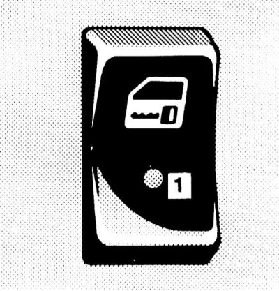
Parktronic switch (PTS)
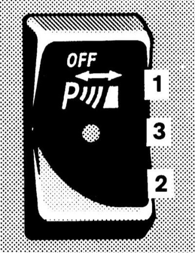
Parktronic switch
1 - PTS disabled
2 - PTS enabled
3 - Control LED
The PTS deactivation key switch is located directly below the selector lever (AT) /shift knob (RKPP) and is equipped with a built-in control LED that is activated when the system is turned off.
The PTS is reactivated automatically when the ignition key is turned to position 2.
Note. Connecting the trailer wiring to the towbar will automatically deactivate the PTS.
The switch of management of functioning of the electric drive of a horizontal/vertical curtain of back glass
The switch for controlling the functioning of the electric rear window blind is located on the center console, on the right under the selector lever (AT) /shift knob (RKPP).
The drive only functions in positions 1 or 2 of the ignition key.
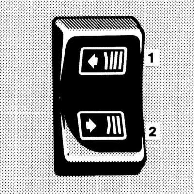
The switch of management of functioning of the electric drive of a horizontal blind of a rear window
1 - close
2 - Open
Switch for controlling the operation of the electric drive vertical (lifting) rear window blinds
1 - Raise
2 - Lower
To close the curtain, press the upper part of the switch button, to open it, press the lower part.
Trip computer
Control Panel
The trip computer control panel is located on the vehicle's center console, directly below the selector lever (AT) /shift knob (RKPP).
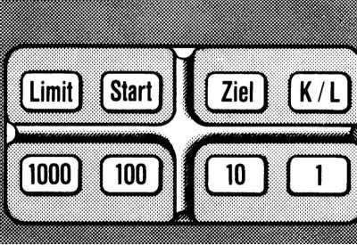
Trip computer control panel
The panel includes three functional buttons:
Display
Note. Models without a trip computer have a glasses compartment instead of the display assembly.
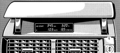
trip computer output display
1 - Lid opening button
The data output display is located in the center of the instrument panel, directly above the cabin ventilation/heating vent assembly, and is equipped with a lift-up cover where the goggles compartment would fit on non-computer models.

Press the button to open the display screen
Note. Lowering the display cover does not stop the operation of the computer, - control of the maximum permissible speed of movement (Limit) continues to be implemented.
The computer is activated when the ignition key is turned to position 2, - a message will be displayed on the display screen «AB START» (From the start) and letter «TO» memory for short distances.
Speed limit control function (Limit)
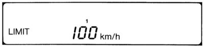
Press the
To confirm the entry, briefly press the
Note. If you enter a speed limit below 10 km/h, the chime is disabled.
Unlocking: Briefly press the
The function of monitoring route parameters from the moment of launch (
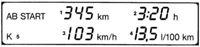
This function allows you to track such route parameters as the distance traveled from the start, travel time, average speed and average fuel consumption.
The mode is activated using the
To reset the data, press the button «
Note. If, after stopping the vehicle, the key is inserted into the steering wheel lock again and turned to position 2, the short distance memory is reset, the message will flash on the display «AB START» and letter «TO». The monitoring data of the last trip is stored as long as the inscription continues to flash «AB START» and letter «TO» (for no more than 2 km). To do this, briefly press thebutton
The function of calculating the parameters of a route of a given length (Ziel)

This function allows you to track such route parameters as the distance to the selected destination (entered by the user), estimated time of arrival, range and average fuel consumption.
Parameters can be calculated in two independent modes: short distance mode (TO) and long distance mode (L). Switching modes is performed using the K / L button, - the corresponding letter is displayed in the left corner of the display screen.
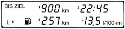
To enter the distance to the intended target, press the
Then, using the number buttons, enter the length of the route, the parameters of which will be monitored by the computer. To confirm the entry, briefly press the
Note. Resetting the data on average fuel consumption is possible in the mode «Start».
When setting the time of the clock built into the instrument cluster (see Section Instrument cluster, meters and control lamps and indicator lights) the current time is automatically shown on the display. The clock is used to calculate the arrival time. To turn off the clock display, press any of the function buttons (
Individual switches for controlling the functioning of the power windows of the rear doors
Key switches are mounted in the armrests of the rear doors. The principle of their operation is similar to that described above for the respective main switches (see Instrument cluster, meters and control lamps and indicator lights).
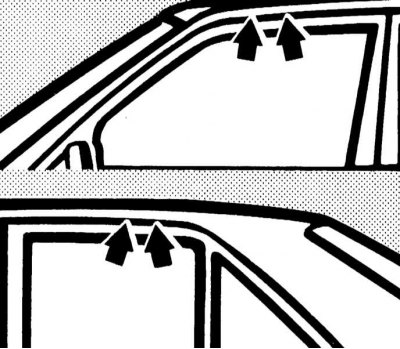
Protection of rear-view mirrors from blinding the driver by reflected light
Driver's door outside rear view mirror with automatic anti-dazzle
The protection is activated automatically when the key in the ignition lock is turned to position 2, - the mirror switches to the appropriate mode depending on the angle of incidence of light rays on its reflective surface.
Note. The activation of the safety switch will only occur if the light hits the mirror-mounted sensors unhindered. This condition may not be met when towing a trailer or closing the rear window shade.
Note. When reverse gear is engaged, as well as when interior lighting is activated, the anti-dazzle protection of the mirror is blocked.
Switching modes of the interior rear-view mirror
Mirror with manual switching
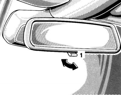
Salon rear-view mirror with manual switching has two fixed positions: day and night. Switching is carried out using a lever mounted in the lower part of the spherical support of the mirror.
Mirror with automatic protection
The principle of operation of the automatic protection of the interior mirror is similar to that described above for the exterior mirror of the driver's door.
Ashtrays and cigarette lighters
The ashtray and cigarette lighter assemblies are mounted in the front section of the center console and in the upholstery panel of the rear doors of the car and have an almost identical design.
To pull the ashtray / cigarette lighter out of the console panel / door upholstery panel, press on the upper edge of its cover - when the cover is released, the assembly will automatically slide out of the panel.
 |  |
Removing the receiving element of the ashtray for cleaning is carried out by wringing out the locking tab, - releasing the lock in this way, remove the element by pulling it up.
Note. On models of the corresponding configuration, before removing the receiving element of the console ashtray, move the AT selector lever to the position «N».
Cigarette lighters can only be used in positions 1 or 2 of the ignition key.
To activate the cigarette lighter, simply push its button into the socket until it stops, - after the heating element has warmed up, the button will automatically jump out to its original position.
Note. In no case do not hold the cigarette lighter button in the pressed position by force! If the cigarette lighter button after pressing does not pop up after more than 30 seconds, the car should be driven to a workshop to have the problem rectified. After use, do not forget to return the button to the socket (to avoid contamination of the).
The cigarette lighter socket can be used to connect external power consumers (pump, cordless phone charger, vacuum cleaner), designed for power supply at 12 V and with a power consumption of not more than 120 watts.
Interior lighting
Main saloon lights and front navigation lamps
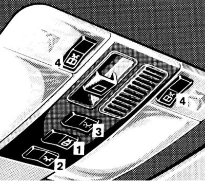
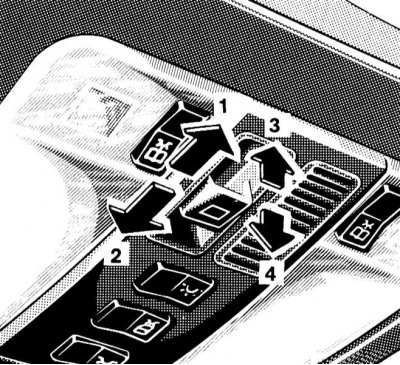
The main control panel for the operation of saloon lamps / electric drive of the sunroof
1 - Switch for activating the interior lighting when opening the doors
2 — the Switch of the main saloon lamp
3 — the Switch of back saloon lamps
4 — Switches of the forward directional lamps (navigation lamps)
The main control panel for the operation of interior lamps / electric drive of the sunroof is built into the assembly of the overhead console of the car.
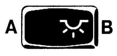
With the middle of the three rocker switches

the activation / deactivation of the interior lighting activation mode is performed when the doors are opened. In position B of the switch, interior lights are activated automatically when any of the doors are opened, in position A, such activation does not occur. In the automatic operation mode, the lamps are turned off automatically by a timer signal when the doors are closed or when the ignition is turned on.
Note. If none of the doors opens when the car is unlocked from the outside, the lamps are activated with a certain time delay.
Front switch

allows forced activation (IN) /shutdown (A) main saloon lamp.
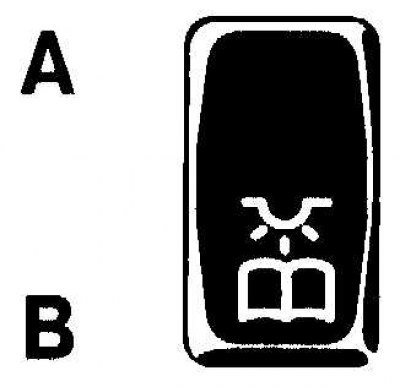
Rear switch
serves to enable (IN) /shutdown (A) rear interior lights.
Note. Turning off the rear interior lights is not possible if any of the rear doors are open.
With two side switches
front lights turn on (navigation lamps). In position B of the switch the light is on, in position A it is off.
Rear spotlights (reading lamps)
Activation of rear spotlights (reading lamps) made using built-in push-button switches. To turn off the lamp, press the button again.
Door sill lights when opening doors
Lights are activated automatically by contact switches.
Managing the functioning of the electric drive of the roof hatch
The principle of operation of the switch for controlling the operation of the electric drive of the roof hatch
1 - Move
2 - Push in
3 - Raise
4 - Lower
The slide/tilt sunroof operation control switch is located on the overhead console.
The electric sunroof operates only in positions 1 or 2 of the ignition key, as well as in position 0 with any of the front doors of the car open.
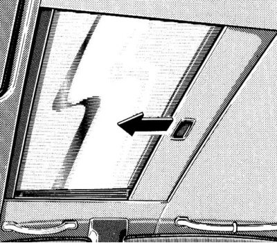
The glass sunroof is equipped with a sunblind that can be opened and closed manually.
Note. Sliding the sunroof to the open position also moves the blind.
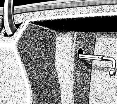
In case of failure of the electric drive, it is possible to close the hatch cover manually. Access to the mechanical drive is provided from the left side of the luggage compartment. Insert a hex wrench equipped with a knob into the hole in the side upholstery, turning the key clockwise allows you to close the shifted hatch cover, against - to lower the raised one.
Sun visors
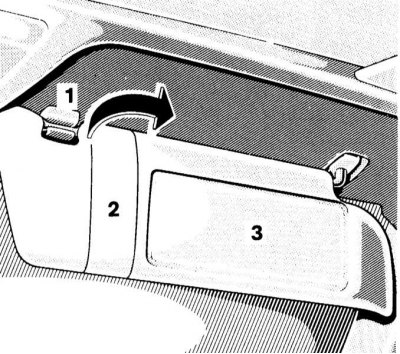
The sun visors protect the eyes of the driver/front passenger from direct sunlight from both the front and the side.
A vanity mirror equipped with a hinged cover is additionally mounted in the passenger sun visor. Opening the mirror cover with the ignition on (key in position 1 or 2) leads to the activation of the mirror illumination.
Rear vanity mirror
The rear vanity mirror is integrated into the headliner. To lower the mirror, lightly press on its cover.
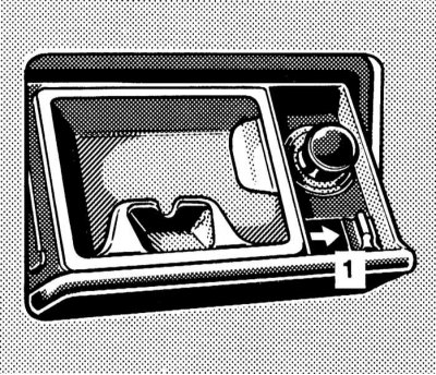
Glove boxes
The main glove box is equipped on the right side of the instrument panel and is equipped with a lock. The release of the lock latch can be done using a special button located directly under the lock cylinder, to the right of the deflectors of the central air ducts of the instrument panel.
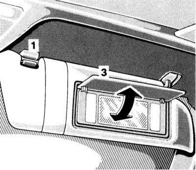
On models not equipped with a trip computer, a goggles storage compartment is placed directly above the central instrument panel vents.
Note. On trip computer models, the data output display is located here. The cover of the compartment is locked with the same lock as the glove box, the latch of the lock can be released using the button located directly above the lock cylinder.
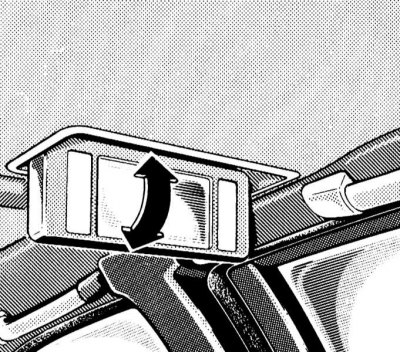
Console glove box
6 - Open
7 - Close
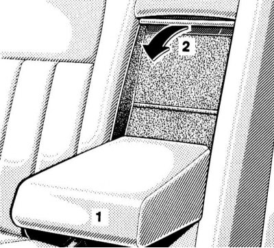
Another stowage box can be equipped in the center console assembly, under the armrest between the front seats of the car - lift the armrest, then open the sliding cover of the box.
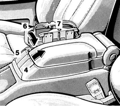
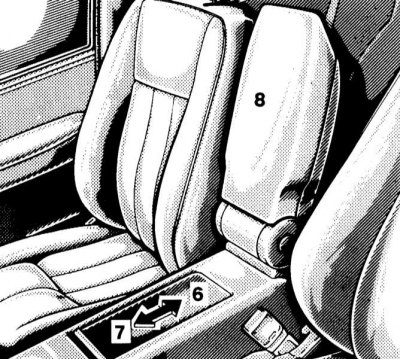
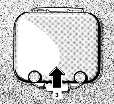
Cantilevered armrest with mobile phone storage and fold-out cup holder panel
4 - Button for releasing the latch of the cover of the compartment for storing a mobile phone
5 - Button for releasing the latch of the cup holder panel
6 - Cup holder panel
7 - Button for releasing the latch of the cup holder panel in the deployed position
On some models, instead of a console box, a lidded compartment for storing a mobile phone and a folding panel with cup holders are equipped - when folded, the assembly forms an armrest.
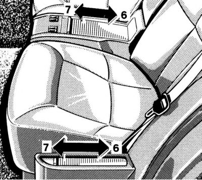
Rear storage boxes
6 - Open
7 - Close
Boxes of a similar design (with sliding lid) are also provided in the rear of the cabin.
First aid kit
Rear storage boxes
1 - Recess for prying the cover
The regular first-aid kit is equipped in the rear shelf of the passenger compartment and is equipped with a hinged lid. To open the cover, pry it from the specially provided recess. Periodically check the contents of the first aid kit for completeness.
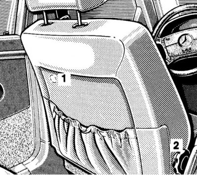
Fire extinguisher
A regular place for attaching a fire extinguisher is equipped on the front side of the driver's seat cushion. After each use, the fire extinguisher must be refueled. The fire extinguisher should be checked every 1-2 years.
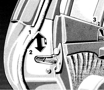
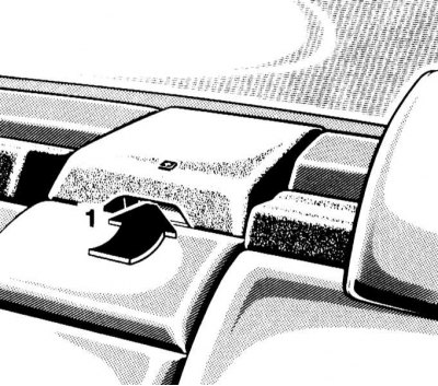
Removal and installation of head restraints of forward seats
To remove the head restraint raised to its highest position, press the release button (1).
1 - Latch release button
2 — the Handle of a mechanical drive of a head restraint (pull out)
Manual head restraint removal differential, turn the extended mechanical drive handle (see Section Seat adjustment) until the headrest is in its highest position, then remove it manually by first pressing the release button.
On models with electric drive, the procedure is similar, with the only difference being that the head restraint is moved to the upper position using the appropriate door switch (see Section Seat adjustment).
Installation is in the reverse order.
Removal and installation of a pillow of a multi-seat back seat
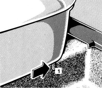
Squeeze out the locking levers located in the deaf bottom edge of the pillow, then lift the front edge of the pillow.
When installing the pillow, make sure that its rear edge is pushed under the backrest until it stops. While pressing the front edge, snap the latches.
Ski transportation
Transportation of skis in the car
Note. The protective case is designed for one pair of skis.
On some models, the back of the rear bench seat has a direct access window to the luggage compartment equipped with a cover, which allows you to freely transport long sports equipment such as skis, etc. in the car.
Lower the rear armrest and flap.
Pull the ski bag folded under the cover into the vehicle interior.
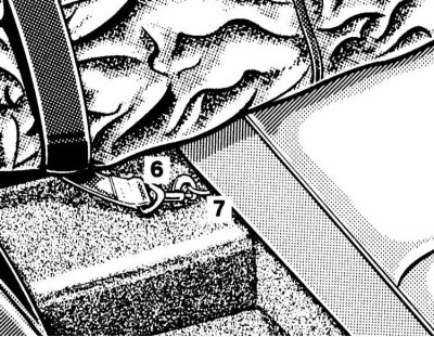
From the luggage compartment side, lift the access hatch cover. The cover is held in the raised position by two magnets.
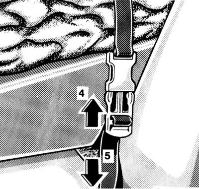
Tuck the skis into the bag and attach the latter to the armrest of the rear seat with straps.
Having fitted the belt, snap the safety carabiner into a special loop.
Folding the cover is done in the reverse order - do not forget to close the cover of the access hatch in the luggage compartment.
Attention! Removing and installing the ski bag assembly
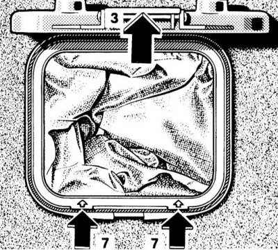
If necessary, the ski bag can be removed from the back of the rear seat (e.g. for cleaning or drying), and the vacated space is used as an additional glove box. Raise the access hatch cover and secure it with magnets, depress the locking tabs marked with arrows in the hatch trim, then remove the cover frame by pulling it back out of the seatback. Installing the cover in place is done in the reverse order - the upper edge of the frame is fixed in a special hole in the upper side of the opening. Track reliability of a latching of the bottom clamps.
Transportation of skis on the roof of the car
For transporting skis on the roof of a car, a regular roof rack or a special ski holder of a proprietary Mercedes-Benz design can be used.
Attach the rack/holder only to the standard attachment points, strictly follow the manufacturer's instructions.