



Diesel engine V6 OM606 car Mercedes S-Class (W140)

Cylinder Head Cover — Installation Details
Cylinder Head Cover Installation Details 1 — Bushing 2 - Seals 7 — Cylinder head cover 8 — Gasket 29/11 — AT control cable
Cylinder Head Cover Installation Details 1 — Bushing 2 - Seals 7 — Cylinder head cover 8 — Gasket 29/11 — AT control cable

Removal and installation of pre-chambers
Pre-chamber installation details 01 - Key; 02 - Puller; 8 - Cylinder head cover; 9 - Bushing; 18 - Nozzle; 19 - Glow plug; 21 - Threaded ring; 23 - Antechamber Removal...
Pre-chamber installation details 01 - Key; 02 - Puller; 8 - Cylinder head cover; 9 - Bushing; 18 - Nozzle; 19 - Glow plug; 21 - Threaded ring; 23 - Antechamber Removal...

Removal and installation the camshaft housing
Camshaft Housing Installation Details 2 - Timing chain tensioner; 3 - Sealing; 6 - Intake camshaft; 7 - Exhaust camshaft; 10 - Camshaft housing; 12 - Sealing ring; 13 -...
Camshaft Housing Installation Details 2 - Timing chain tensioner; 3 - Sealing; 6 - Intake camshaft; 7 - Exhaust camshaft; 10 - Camshaft housing; 12 - Sealing ring; 13 -...

Removal and installation camshafts
Camshaft Installation Details 1 - Rod; 2 - Intake camshaft; 3 - Guide pin; 4 - Bolt; 5 - Camshaft sprocket; 6 - Intake camshaft; 7 - Exhaust camshaft; 8 - Camshaft...
Camshaft Installation Details 1 - Rod; 2 - Intake camshaft; 3 - Guide pin; 4 - Bolt; 5 - Camshaft sprocket; 6 - Intake camshaft; 7 - Exhaust camshaft; 8 - Camshaft...

Checking the control position of the camshafts
Checking the control position of the camshafts 1. Set the piston of the first cylinder to the TDC position. 2. Lock the intake camshaft with the rod (1). To do this,...
Checking the control position of the camshafts 1. Set the piston of the first cylinder to the TDC position. 2. Lock the intake camshaft with the rod (1). To do this,...

Removal and installation the cylinder head
Removal Cylinder head installation details 1. Disconnect the negative cable from the battery. 2. Remove the lower protective shield. 3. Drain the coolant. 4. Remove the...
Removal Cylinder head installation details 1. Disconnect the negative cable from the battery. 2. Remove the lower protective shield. 3. Drain the coolant. 4. Remove the...

Removal and installation the timing chain cover
Removal Timing Chain Cover Installation Details 1. Disconnect the negative cable from the battery. 2. Remove the compressed air supply tube (3). 3. Remove the fan...
Removal Timing Chain Cover Installation Details 1. Disconnect the negative cable from the battery. 2. Remove the compressed air supply tube (3). 3. Remove the fan...

Timing Chain Tensioner — Installation Details
Timing Chain Tensioner Installation Details 7 - Timing chain tensioner; 8 - Sealing ring; 225 - Cork; 226 - Aluminum Gasket; 227 - Ball (diameter 5 mm); 228 - Ball...
Timing Chain Tensioner Installation Details 7 - Timing chain tensioner; 8 - Sealing ring; 225 - Cork; 226 - Aluminum Gasket; 227 - Ball (diameter 5 mm); 228 - Ball...
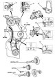
Timing Drive — General Information, Component Maintenance
Note: The timing chain can be replaced without disassembling the engine. Using the tools listed below, the new chain can be connected to the old one, threaded around the...
Note: The timing chain can be replaced without disassembling the engine. Using the tools listed below, the new chain can be connected to the old one, threaded around the...

Checking the condition of the valves
The dimensional characteristics of the valves are given in Specifications . Valve sizes
The dimensional characteristics of the valves are given in Specifications . Valve sizes

Removal, inspection and installation of valve guide bushings
Removal, checking and installation the valve guide bushing A - Knocking out the guide bushing; B - Check; C - Boring of the cylinder head hole to the 1st nominal size; D...
Removal, checking and installation the valve guide bushing A - Knocking out the guide bushing; B - Check; C - Boring of the cylinder head hole to the 1st nominal size; D...

Replacing valve seats
Milling and grinding of valve seats Processing 1. Remove the valves. 2. Check the valve guides. 3. Grind the valve seats. 4. Check the valves for leaks. 5. Measure the...
Milling and grinding of valve seats Processing 1. Remove the valves. 2. Check the valve guides. 3. Grind the valve seats. 4. Check the valves for leaks. 5. Measure the...

Removal and installation pistons
See Section Removal and installation pistons subject to the following amendments: The amount of piston protrusion On a new cylinder block 0.785-1.015 mm On a ground...
See Section Removal and installation pistons subject to the following amendments: The amount of piston protrusion On a new cylinder block 0.785-1.015 mm On a ground...

Removal and installation piston rings
Removal Piston rings 1 - Upper compression ring; 2 - Lower compression ring; 3 - Oil scraper ring; 4 - Oil scraper ring spring; 6 - Oil scraper ring notches; 10 - Pliers...
Removal Piston rings 1 - Upper compression ring; 2 - Lower compression ring; 3 - Oil scraper ring; 4 - Oil scraper ring spring; 6 - Oil scraper ring notches; 10 - Pliers...

Removal, condition check and installation of connecting rods
Removal Remove the pistons (see section Removal and installation piston rings ). Examination Checking the diameters of the upper and lower connecting rod heads using an...
Removal Remove the pistons (see section Removal and installation piston rings ). Examination Checking the diameters of the upper and lower connecting rod heads using an...

Measuring cylinder diameters
The measurement of the cylinder diameters is carried out in the longitudinal A and transverse B directions A - Longitudinal direction; B - Transverse direction; a -...
The measurement of the cylinder diameters is carried out in the longitudinal A and transverse B directions A - Longitudinal direction; B - Transverse direction; a -...

Checking the condition of the crankshaft, replacing the seals
Examination See Section Checking the condition of the crankshaft . The dimensional characteristics, the values of the working clearances of the bearings and the axial...
Examination See Section Checking the condition of the crankshaft . The dimensional characteristics, the values of the working clearances of the bearings and the axial...

Removal and installation the engine oil pan
Removal Engine Oil Pan Installation Details 1. Disconnect the negative cable from the battery. 2. Lift the engine casing and secure it over the fan. 3. Unscrew the front...
Removal Engine Oil Pan Installation Details 1. Disconnect the negative cable from the battery. 2. Lift the engine casing and secure it over the fan. 3. Unscrew the front...

Removal and installation the oil pump
Removal Oil pump installation details A - Oil pump version 1; 10 - Pallet; 24 - Oil pump (1st version); 25 - Oil pump sprocket (1st version); 27 - Guide bushings (1st...
Removal Oil pump installation details A - Oil pump version 1; 10 - Pallet; 24 - Oil pump (1st version); 25 - Oil pump sprocket (1st version); 27 - Guide bushings (1st...

Oil Level Switch Sensor — Installation Details
Oil Level Switch Installation Details 1 - Pallet 4 — Sealing ring S43 — Oil level sensor
Oil Level Switch Installation Details 1 - Pallet 4 — Sealing ring S43 — Oil level sensor

Removal and installation the oil filter housing
Removal Oil filter housing installation details 8 - Guide bushings; 9 - Oil filter gasket; 10 - Oil filter housing; 15 - Sealing rings 24 - Connector; 25 - Cooling...
Removal Oil filter housing installation details 8 - Guide bushings; 9 - Oil filter gasket; 10 - Oil filter housing; 15 - Sealing rings 24 - Connector; 25 - Cooling...

Oil Cooler Fan — Installation Details
Oil Cooler Fan Installation Details 1 - Bolts 4.8x13; 2 - Bracket; 3 - Fan shroud; 4 - Oil radiator; 5 - Radiator fan; 6 - Bolts M6x16; 7 - Gaskets 6.2x18; 8 -...
Oil Cooler Fan Installation Details 1 - Bolts 4.8x13; 2 - Bracket; 3 - Fan shroud; 4 - Oil radiator; 5 - Radiator fan; 6 - Bolts M6x16; 7 - Gaskets 6.2x18; 8 -...
This section is available on: russian, bulgarian, belarusian, ukrainian, serbian, croatian, romanian, polish, slovak, hungarian
Link in different formats to this section
TEXTHTMLBB Code
- General information
- Introduction to guide
- User manual
- Maintenance
- Power unit
- Engine repair
- Cooling and heating systems
- Power and exhaust systems
- Ignition and control system
- Charge and launch systems
- Transmission
- Automatic gearbox
- Drive shafts
- Chassis
- Brake system
- Front suspension
- Rear suspension
- Steering
- Body
- Body elements
- Electrical equipment
- Equipment and devices
- Electrical circuits
- User manual
- Controls and instruments
- Driving and operation
- Maintenance
- Power unit
- Petrol engine V6
- Petrol engine V8
- Petrol engine V12
- Diesel engine OM603
- Diesel engine OM606
- Cooling system
- Power supply and injection system
- Control system HFM-SFI
- Control system LH-SFI
- Control systems ME-SFI
- Diesel control system
- Ignition system
- Charge and launch system
- Transmission
- Mechanical gearbox 717.438
- Mechanical gearbox 717.454
- Automatic gearbox 722.5
- Automatic gearbox 722.6
- Clutch and drive shafts
- Differential
- Chassis
- Brake system
- Steering
- Front suspension
- Rear suspension
- Body
- Exterior (external elements)
- Interior (internal elements)
- Electrical equipment
- Equipment and devices
- Electrical circuits
- General information
- Introduction to guide
- Power unit
- 8-cylinder V8 engine
- 6-cylinder I6 engine
- Cooling and lubrication system
- Power system (carburetor)
- Fuel injection system
- Ignition system
- Transmission
- Clutch and cardan
- Car gearbox
- Chassis
- Front suspension
- Rear suspension
- Steering
- Brake system
- Electrical equipment
- Power devices
- Electrical circuits