
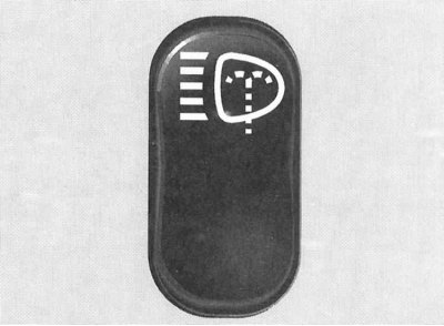
Switching the operating modes of the headlights and activating the direction indicators
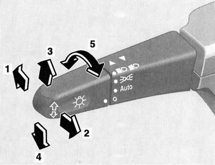
1 - Position «high beam»; 2 - High beam signaling; 3 - Activation of right turn indicators; 4 - Activation of left turn indicators; 5 - Selecting the mode of operation of external lighting devices (Off/Auto Select/Driving Lights/Low and High Beams/Parking Lights)
Switches located on the steering column
Combination switch
Left combination stalk (selection of operating modes of external lighting devices, activation of direction indicators).
Using the rotary knob at the end of the stalk lever, one of the following modes of operation of the exterior lighting can be selected:
ABOUT Lighting devices are off
AUTO Automatic selection of the operating mode of lighting devices depending on the lighting conditions.
 Switching the headlights from the low beam mode to the high beam mode is done by pressing the steering column switch lever away from you, - the corresponding control lamp of the characteristic blue light should automatically light up on the instrument panel (see above). To turn off the high beam, return the lever to its original position.
The possibility of high beam signaling is also provided: the signaling is carried out by pulling the stalk lever towards you and regardless of the selected position of the handle for selecting the mode of operation of the external lighting devices (see above).
Note. High beam signaling remains possible even when the ignition is switched off.
The direction indicators are activated by pushing the left stalk lever in the appropriate direction. The lever is moved up or down, depending on the selected direction of change of course.
When moving the lever to the extreme upper/lower position (click) the corresponding direction indicators will continue to function until the steering wheel is returned to the straight-ahead position (the limit switch will work), or until the lever is returned to neutral.
Note. Short-term inclusion of pointers, for example, with the intention to change the lane of movement, is done by slightly pulling the lever up or down.
Windshield wiper/washer control
Activation of windshield wipers and washers and headlight lenses is only possible with the ignition on (key in position 1 or 2). The choice of the operating mode of the wipers is made by moving the switch lever in the vertical plane:
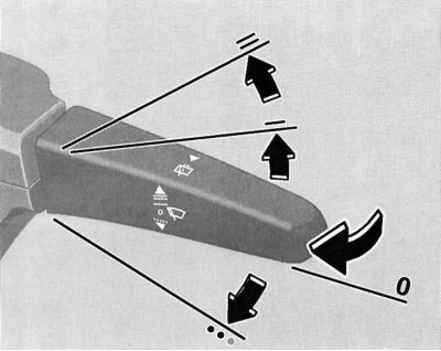
Windshield wiper/washer control
O Off
---- Interval mode
—— Normal speed continuous wiper
=== High speed continuous wipers
Note. When the speed of the car exceeds the value of 170 km / h, the interval mode of operation of the wipers automatically changes to continuous.
On models equipped with a rain sensor, the activation of the intermittent wiper operation leads to a single operation of the wipers, followed by an automatic selection of the pause duration depending on the intensity of wetting the glass surface.
Washers are activated by pulling the switch lever towards you, the supply of washer fluid is accompanied by several strokes of the wiper blades.
Note. When the car comes to a complete stop and one of the front doors is open, the intermittent operation of the wipers is suspended, which helps prevent the moisture brushed off from getting on the clothes of the driver / passenger entering or leaving the car.
Steering column switch for speed control/Speedtronic variable speed limiter
The tempostat function control switch is located on the steering column above the combined steering column switch.
A detailed description of the principles of controlling the functioning of the tempostat is given in Section Speed control systems (Tempostat/Speedtronic).
Horn activation button
The horn button is built into the hub of the steering wheel.
Switches and controls located on the instrument panel
Headlight beam tilt adjuster
The roller switch for adjusting the tilt of the optical axes of the headlights is located on the left side of the instrument panel and has four fixed positions (0, 1, 2 and 3).
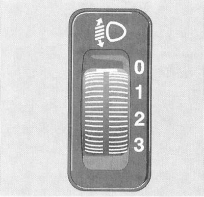
Headlight beam tilt adjuster
The switch serves to adjust the lighting distance (when turning on the low beam), in order to prevent blinding of drivers of oncoming and ahead vehicles.
Regulator (see resist. illustration) should be set to position (according to the tables below), corresponding to the number of passengers and the degree of vehicle loading.
Models with adjustable ride height
See table.
| Switch position | Number of people in the front seats | Number of people in the rear seats | Cargo in the luggage compartment |
| 0 | 1 or 2 | 0 | Absent |
| 1 | 2 | 3 | Absent |
| 2 | 2 | 3+2 on third row folding seats | Full load |
| 3 | 1 | 0 | Full load |
Parking brake release handle
The models covered in this manual use a foot operated parking brake. The parking brake is applied by depressing the pedal located on the left under the instrument panel. The parking brake release handle is on the left of the vehicle's instrument panel and is marked with a pictogram of the corresponding content.
Pulling the handle causes the parking brake to be released instantly, - the corresponding indicator lamp (see Section Instrument cluster, meters and control lamps and indicator lights) on the instrument panel should go out.
Steering wheel adjustment
The lock release lever is located on the left side of the steering column. To release the lock, push the lever all the way down, then adjust the steering wheel height to suit your body type. Having achieved a comfortable position of the steering wheel, press the lever up.
Note. The corresponding control lamp on the instrument cluster of the car warns about disabling the lock of the adjusting mechanism of the driver (see Section Instrument cluster, meters and control lamps and indicator lights).
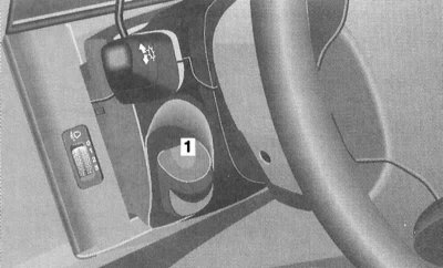
Lever location (1) steering column lock release drive
Headlight wiper activation switch (models equipped with bi-xenon headlights)
The headlight cleaning switch is located on the dashboard of the car, to the right of the steering column. Activation of the headlamp cleaners is possible only in position 2 of the key in the ignition lock.
Headlight wiper activation switch (models equipped with bi-xenon headlights)
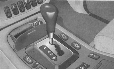
Ignition switch/steering column lock
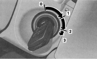
The ignition lock has four fixed positions
The ignition switch is located on the right side of the steering column. The key can occupy one of four fixed positions in the lock:
- 0: Steering column lock
- 1: Auxiliary electrical consumers (parking position)
- 2: Ignition on/Drive
- 3: Engine start
Position 0 - steering column lock
The key can only be entered or removed from the lock in this position. Turning the ignition key from position 0 to position 1 unlocks the steering column. In addition, on models equipped with an automatic transmission, an additional condition for starting permission is the mandatory transfer of the selector lever to the position «R».
The key can only be removed from the ignition switch after turning it to position 0.
Note. On models with AT, removing the key from the ignition lock becomes possible only after moving the selector lever to the position «R».
The steering column is locked automatically when you try to turn the steering wheel after removing the key from the ignition.
The steering column lock sometimes results in the inability to turn the key in the ignition. In such a situation, turn the steering wheel slightly in one direction or another (in order to relieve the burden), while turning the key in the lock.
Attention! Never remove the key from the ignition lock while driving! This will inevitably lead to steering column lock and loss of control. Remove the key from the lock only after the vehicle has come to a complete stop!
Note. With the front door open, it remains possible to activate the electric seat adjustment, steering column, power windows and sunroof cover with the key removed from the ignition switch.
Position 1 - parking
In this position of the ignition key, the auxiliary consumers of electricity can operate (audio system, cigarette lighter, heater fan, windshield wipers, etc.).
Position 2 - ignition on/driving
In this position, the ignition key is constantly while the car is moving, as well as when the engine is idling. On diesel models, turning the key to position 2 before starting the engine activates the preheating system. At the same time, electrical power is provided to all systems and additional equipment installed on the vehicle. When the key is turned from position 1 to position 2, some of the control lamps located on the dashboard of the car briefly turn on, confirming the correct functioning of the corresponding control systems (see Section Instrument cluster, meters and control lamps and indicator lights).
Position 3 - start
Turning the key to this position engages the starter. After starting the engine, the key must be released and it will automatically return to position 2.
Hazard switch
The alarm is activated using a button located on top of the steering column. The switch button is equipped as standard with a signal lamp with a pictogram depicting two triangles inscribed in each other.
Turning on the alarm leads to the simultaneous operation of all four direction indicators (and their indicator lights on the vehicle's instrument cluster). The alarm system is designed to warn other road users about the forced stop of the car and is also used in other dangerous situations provided for by traffic rules. To turn off the alarm, press the switch button again.
Note. The alarm is activated automatically when any of the airbags is deployed.
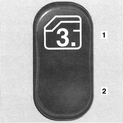
LOW RANGE mode switch (for off-road driving)
Note. The LOW RANGE mode is designed for driving in off-road conditions, overcoming water obstacles, towing a trailer in hilly terrain.
The off-road LOW RANGE activation switch is located in the upper left corner of the console section of the instrument panel. To turn on the down mode, move the selector lever to the position «N» (models with AT) / depress the clutch and foot brake pedals (models with manual transmission), then press the upper part of the pushbutton once, - indicator lamp «LOW RANGE» (see Section Instrument cluster, meters and control lamps and indicator lights) on the instrument cluster should flash three times, then switch to a constant glow. In the event of a failure to turn on the step-down mode, the control lamp will flash at a double frequency.
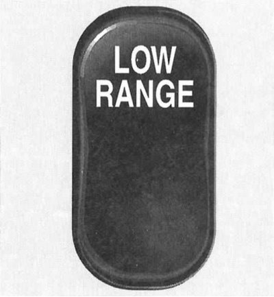
LOW RANGE activation switch for off-road driving
Return to the normal driving mode is carried out in a similar manner - the control lamp should flash three times, then go out, confirming the reduction mode is off.
Attention! Activation of the mode should be made only after a complete stop of the car! When driving in the LOW RANGE mode, try not to increase the engine speed above 1500 per minute!
Fog Light Activation Switch
The fog light activation switch is located on the left-hand side of the center console section of the instrument panel, next to the storage compartment. Fog lights can only be activated when the exterior lights are in working order and the dipped beam headlights are on (see above). To turn on the fog lights, turn on the dipped beam (see above), then press the upper part of the key switch, - the corresponding indicator light on the instrument cluster should light up (see Section Instrument cluster, meters and control lamps and indicator lights).
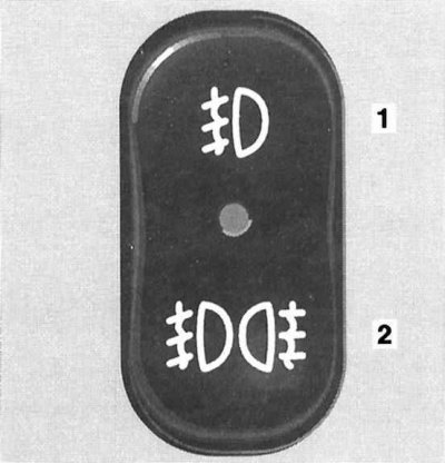
Fog lamp activation switch (1) /rear fog lamps (2)
To turn on, in addition to the fog lights, the rear fog lights, you must press the bottom of the key switch - the control LED built into the switch assembly should light up.
When the automatic operation mode of the external lighting devices is activated, when the engine is started, in addition to the standard running lights (dimensions, license plate light) the rear fog lamp is also activated.
With this switch, the delay time for turning off the headlights when closing the doors is also set - the upper part of the button should be kept pressed until the desired delay time is displayed on the instrument cluster display (the rotary handle of the left stalk switch must be turned to position O).
If none of the vehicle doors are opened after the engine is turned off, or if all the doors are not fully closed after opening, the headlight off delay function will be deactivated automatically after approximately 1 minute.
Note. Within 10 minutes after closing the doors, the function can be reactivated by opening any of the doors.
Front seat heating switches
Two key switches for heated seats are located at the edges of the lower row of switches in the console section of the instrument panel and allow you to activate two modes of seat heating (normal and fast), and turn off the heaters.
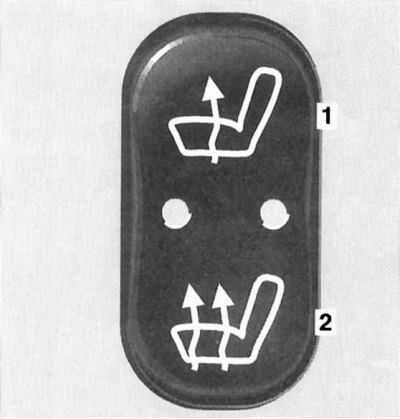
Seat heating switch
1 - Normal heating
2 - Accelerated heating
The seat heating is only activated when the engine is running.
Activation of the normal mode is accompanied by the operation of one of the two control LEDs built into the switch. During accelerated heating, both LEDs light up.
The heating is turned off as follows: if one built-in control LED is on, press the upper part of the button of the corresponding switch, two - the lower one. Automatic shutdown of the heating elements occurs at the timer signal after approximately 20 minutes of continuous operation of the heating elements.
Note. The seat heating is also switched off when the charging system is overloaded or the battery charge level is insufficient - in this situation, one or both control diodes (depending on the selected heating mode) switch to flash mode. After removing overload (disconnection of excess electricity consumers) the seat heating will be activated automatically.
Switches for the electric drive of the rear rotary side windows
The key switches for the electric drive of the rear rotary side windows are located second from the edges of the lower row of switches in the console section of the instrument panel. Pressing the upper part of the switch opens the corresponding window, the lower part closes it.
Note. The power rear tilting side windows continue to function for 30 minutes after opening any of the front doors (even if the ignition key is turned to position 0), - function «Comfort».
Power switch for rear swing side window
1 - Open
2 - Close
Rear window wiper/washer operation control switch
Equipped with a control LED, the key switch for controlling the functioning of the rear window wiper / washer is located in the central part of the lower row of switches in the console section of the instrument panel. Pressing the upper part of the switch activates the rear wiper in interval mode, - to turn off the wiper, press the same button again.
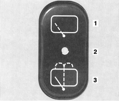
Rear window wiper/washer operation control switch
1 - Activation of the intermittent wiper mode
2 - Control LED
3 — Activation of the glass washer
Activation of the washer fluid supply to the rear window is carried out by holding down the lower part of the switch button - at the same time the wiper is also activated, which will continue to operate for about 5 seconds after releasing the button.
Note. If the intermittent wiper operation has been enabled, stopping the washer fluid does not turn it off.
On rain-sensing models, rear wiper interval settings are adjusted automatically (provided the front wipers are also set to intermittent).
Anti-skid switch (ESP)
Anti-skid switch (ESP) is placed in the central part of the lower row of switches of the console section of the instrument panel. The need to disable the ESP system may arise when driving with snow chains, in deep snow, sand or gravel. In this case, the engine torque is no longer controlled and the slipping of the drive wheels can have a milling effect on the ground.
To turn off the ESP, press the upper part of the switch button, - the control lamp mounted in the speedometer dial should light up on the instrument cluster (see Section Instrument cluster, meters and control lamps and indicator lights).
To return to normal driving mode, just press the bottom of the switch button.
Air conditioning control panel
See Section Comfort.
Audio control panel
See Section Comfort.
Switches located on the center console
Power window operation control switches
Four individual switches for controlling the functioning of the electric door window regulators are located on the center console to the right and left of the AT selector lever / gear shift knob assembly (RKPP). Two more individual switches for controlling the power windows of the rear doors are located on the rear end of the center console.
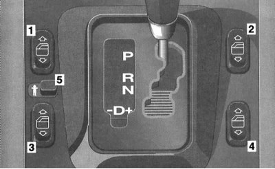
Power Window Switches
1 - Power window of the left front door; 2 - Power window of the right front door; 3 - Power window of the left rear door; 4 - Power window of the right rear door; 5 - Switch for blocking individual rear window switches
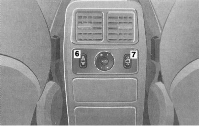
Rear Power Window Individual Switches
6 - Power window of the right rear door; 7 - Switch for blocking individual rear window switches
Each switch allows you to activate the power window regulator drive of the corresponding door. The slider located between the left door switches allows, if necessary, blocking the possibility of activating the rear door window regulators from individual door switches by shifting it to the right - an icon with the image of a little man should open.
The power windows are only activated when the ignition is on.
Note. The power windows remain active for an additional 30 minutes after either front door is opened (even with the ignition key turned to position 0), - function «Comfort».
To lower the glass, press the bottom of the corresponding key switch. Pressing the top of the switch allows you to move the glass to the up position. Pressing the switch button over the point of resistance leads to the automatic lowering/raising of the glass of the respective door.
Note. If the window encounters resistance when moving to the upper position, the electric drive of the regulator is immediately blocked, while the glass goes down a little, and further holding down the upper part of the key will only lower the window to the lower position.
The adjustment of the door windows should be carried out every time after turning off the on-board power / discharging the battery, as well as after repeatedly pressing the switch without moving the glass to the end position. To perform the adjustment, turn the key in the ignition switch to position 2, press and hold the top of the relevant rocker switch until the window rises plus approximately 1 second.
Single lock switch
The single lock switch is located on the center console on the left behind the gear lever / AT selector and allows the single lock to be activated from the passenger compartment - all doors must be closed.
Note. If the doors were locked using the remote control, unlocking the locks using the switch is not possible.
Parktronic switch (PTS)
Note. The principle of operation of the PTS is described in detail in Section Parktronic system (PTS).
The PTS switch, located on the right side of the center console behind the gear lever/AT selector, has a built-in control LED that is activated when the system is switched off and allows the activation/deactivation of the Parktronic system.
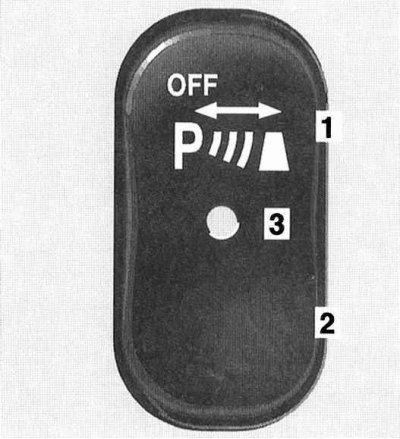
Parktronic switch (PTS)
1 - Off
2 - On
3 - Control LED
The PTS is reactivated automatically when the ignition key is turned to position 2.
Note. Connecting the trailer wiring to the towbar will automatically deactivate the PTS.
Control panel for the functioning of the electric drive for adjusting the door mirrors
Adjustment
The panel is located on the center console behind the gear lever/AT selector.
At the corners of the panel there are buttons for selecting the mirror to be adjusted and push-button switches for folding the mirrors, in the center of the panel there is a rotary control switch for adjusting the position of the mirrors.
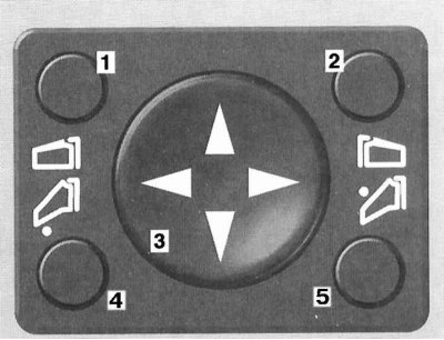
Control panel for the functioning of the electric door mirrors
1 - Switch for activating the electric drive of the left door mirror; 2 - Switch for activating the electric drive of the right door mirror; 3 - Rotary control switch; 4 - Left mirror folding switch; 5 - Right mirror folding switch
The outside rear-view mirrors are spherical in design to widen the field of vision. Heated mirrors work automatically.
Writing adjustment parameters to the processor memory (with appropriate equipment)
Note. The selected position of the exterior mirrors can be stored in the memory of the on-board processor along with the seat position data (see Section Seat adjustment).
Recording the selected position of the rear-view mirrors in the memory of the processor is carried out simultaneously with recording the parameters for adjusting the front seats (see Section Seat adjustment).
The design of the system allows you to record the parking position of the rear-view mirror of the right door. Park the vehicle stationary at the edge of the pavement and leave the ignition on, adjust the right door mirror so that it reflects the curb, then press the processor memory access button and press the power mirror control rotary switch down for about 3 seconds - the mirror should not measure its position, otherwise the procedure should be repeated. Now, before starting to park the car, it will be enough to press the corresponding call button from the memory of the parking position of the right mirror. The mirror returns to its original position automatically when the speed reaches a value of 10 km / h, approximately 10 seconds after the reverse gear is turned off, and also when the button for activating the electric drive of the left door mirror is pressed.
Note. When either front door is opened, the power door mirrors remain active for an additional 30 minutes even with the key turned to position 0 or removed from the ignition, - function «Comfort».
Other switches
Switch for disabling protection devices against towing/unauthorized entry into the car interior
With the appropriate vehicle equipment, the activation of the devices in question occurs automatically when the doors are locked / the anti-theft alarm is activated.
Before scheduled towing/transportation of the vehicle, the safety device must be deactivated.
The switch for activation/deactivation of the towing protection device/volume sensor is located on the overhead console of the car, - turn the key in the ignition switch to position 1, press the OFF button of the switch, then turn the key to position 0 and remove it from the lock.
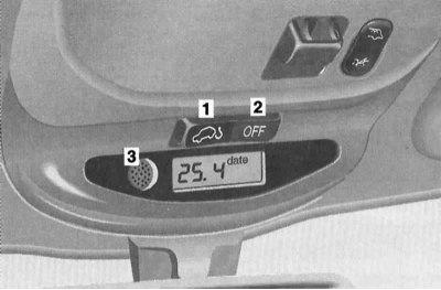
Switch for disabling the towing protection devices
1 - Turn on the device
2 - Turning off the device
3 - Volume sensor
On models equipped with an on-board computer, press the RESET or MODE button on the overhead console control panel within 30 seconds - the message should appear on the display «OFF».
After disabling the device, the car can be locked and the anti-theft alarm can be activated from the remote control. The towing protection device/volume sensor remains disabled until the ignition key is turned to position 1.
The switch of management of functioning of the electric drive of a cover of the top hatch
The slide/tilt sunroof operation control switch is located on the overhead console in front of the saloon lamp.
The principle of controlling the functioning of the electric drive of the top hatch
1 - Control switch
2 - Move
3 - Push in
4 - Raise
5 - Lower
The electric sunroof operates only in positions 1 or 2 of the ignition key, as well as for 30 minutes in position 0 with any of the front doors of the car open (function «Comfort»).
The principle of controlling the cover drive is shown in the illustration, - a short press of the switch leads to the automatic operation of the electric drive (stop can be made by pressing the switch again).
Note. In automatic mode, the sunroof does not open completely (press the switch again if necessary). To move the cover to the required position, keep the switch depressed.
The glass sunroof is equipped with a sunblind that can be opened and closed manually.
Note. Sliding the sunroof to the open position also moves the blind.
In case of failure of the electric drive, it is possible to close the hatch cover manually. Fold out the protective cover and insert a hex key equipped with a knob into the receiving hole of the drive motor shaft, turning the key clockwise allows you to close the shifted hatch cover, against - to lower the lifted one.
Mechanical method of emergency closing of the top hatch cover in case of electric drive failure
Trip computer (with appropriate equipment)
The trip computer control panel is placed on the overhead console of the car in the center console of the car and is equipped with a liquid crystal display and a key switch for setting/selecting operating modes.
The computer is activated automatically when the ignition key is turned to position 2. If the computer is forcibly switched off and the display is not activated, press the MODE button on the rocker switch on the control panel.
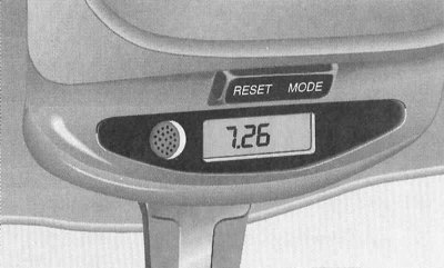
Trip computer control panel
The design of the computer provides eight modes of operation:
- 1. Date
- 2. Compass
- 3. Stopwatch
- 4. Instant fuel consumption
- 5. Average fuel consumption
- 6. Range based on remaining fuel capacity
- 7. Interface language
- 8. Off
Switching between modes is done using the MODE button on the key switch on the control panel.
Date
To enter the setting mode, press the RESET button of the key switch, - the current month will flash on the display screen, - the adjustment is made using the MODE button. A second press of the RESET button leads to the transfer to the mode of setting the day of the week, then the year. Pressing the RESET button a fourth time exits the setting mode.
Compass
In mode «Compass» the display shows the direction of travel:
- N - North
- NO - Northeast
- O - East
- SO - Southeast
- S - South
- SW - Southwest
- W - West
- NW - Northwest
Note. The accuracy of the compass readings can be affected by the proximity of large buildings, bridges, power lines and strong radio sources, as well as the presence of metal and magnetic objects on board the vehicle.

Map of magnetic declination zones
When traveling long distances, it may be necessary to adapt the compass to the conditions of changing magnetic declination zones:
- a) Using a special map of magnetic declinations, determine the zone of your location, - write down the result;
- b) Turn the key in the ignition to position 2;
- With) Keeping the MODE button on the computer control panel pressed, wait for the compass readings to appear on the display screen;
- d) By pressing the RESET button of the key switch, go to the zone selection mode, - the number of the previously selected magnetic declination zone should be displayed on the display screen;
- e) By successive pressing the RESET button, adjust the zone in accordance with the actual location of the car - see paragraph (A);
- f) To exit the setting mode and enter a new value into the processor memory, press the MODE button twice, the compass readings should appear on the display screen.
If the automatic compass corrector does not cope with the task, the necessary calibration can be done manually:
- a) Take the car to an open area;
- b) Switch off all on-board electrical consumers and close all doors, including the tailgate (otherwise, the display screen in compass mode will display «- - -»;
- c) Hold down the MODE button on the key switch and wait for the compass reading to appear on the display;
- d) Click on the reset button (RESET), then again on the MODE button, - the message should appear on the display screen «CAL» (Calibration);
- e) Hold down the RESET button for approximately 2 seconds to enter the calibration mode (the screen is lit up «CAL»);
- f) Moving at a speed of approximately 5÷10 km / h, make a couple of circles, - the inscription «CAL» on the screen should turn off, confirming the completion of the compass calibration.
Note. If the inscription «CAL» does not disappear, then to exit the calibration mode, it is necessary to remove the key from the ignition lock - after the ignition is turned on again, the procedure can be repeated.
Stopwatch
The stopwatch is started and stopped using the RESET button on the key switch on the computer control panel. To reset the stopwatch, hold down the RESET button for a few seconds.
Instant fuel consumption
In this mode, the display screen displays the value of the instantaneous fuel consumption based on the current driving parameters.
Average fuel consumption
The average fuel consumption is reset by pressing the RESET button on the rocker switch.
Cruising range based on remaining fuel capacity
When the key is turned in the ignition switch to position 2, the distance value is displayed on the display screen, the edges can be passed on the fuel reserve in the tank.
Note. When the minimum amount of fuel in the tank is reached, the display screen starts flashing.
Interface language
The interface language is also selected using the RESET button.
Turned off
Pressing the MODE button again will turn off the computer.
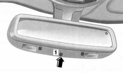
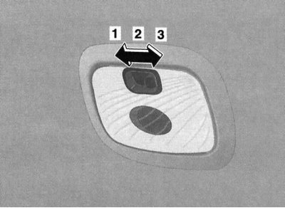
Switching modes of the interior rear-view mirror
Mirror with manual switching
Salon rear-view mirror with manual switching has two fixed positions: day and night. Switching is carried out using a lever mounted in the lower part of the spherical support of the mirror.
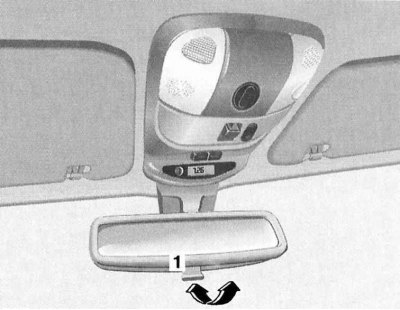
Interior rear-view mirror switch
Mirror with automatic protection
Protection is activated automatically when the key is turned in the ignition switch to position 2, the control LED mounted in the mirror assembly should light up and can be forcibly turned off using the button located next to the LED. In the active state, the mirror switches to the appropriate mode depending on the angle of incidence of light rays on its reflective surface.
Attention! The activation of the safety switch will only occur if the light hits the mirror-mounted sensors unhindered. This condition may not be met when towing a trailer or closing the rear window shade.
Note. When reverse gear is engaged, as well as when interior lighting is activated, the anti-dazzle protection of the mirror is blocked.
Rear view mirror with automatic anti-dazzle
1 — The switch of function of protection against blinding
Ashtrays cigarette lighters
The ashtray and cigarette lighter assemblies are mounted in the middle and rear sections of the car's center console and are almost identical in design.
Assembling the front ashtray (1) with cigarette lighter (2)
Assembling the rear ashtray (1) with cigarette lighter (2)
The front ashtray is opened by briefly pressing the top of the lid. To remove the insert, grab it by the side walls and pull it up.
The rear ashtray is removed by pushing inward and then releasing it, and if necessary, can be completely released from the receptacle.
Attention! Close the ashtray before folding the rear bench seat!
Cigarette lighters can only be used in positions 1 or 2 of the ignition key.
To activate the cigarette lighter, simply push its button into the socket until it stops, - after the heating element has warmed up, the button will automatically jump out to its original position.
Attention! In no case do not hold the cigarette lighter button in the pressed position by force!
If the cigarette lighter button after pressing does not pop up after more than 30 seconds, the car should be driven to a workshop to have the problem rectified. After use, do not forget to return the button to the socket (to avoid contamination of the).
The cigarette lighter socket can be used to connect external power consumers (pump, cordless phone charger, vacuum cleaner), designed for power supply at 12 V and with a power consumption of not more than 50 watts.
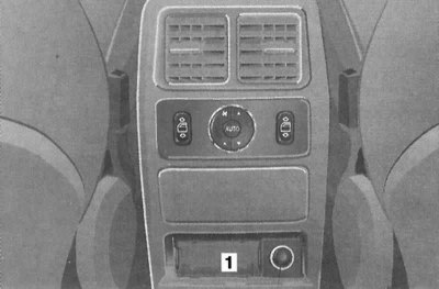
Power outlets
One power socket is located in the front passenger's footwell, and one more in the luggage compartment of the vehicle.
The sockets are equipped with protective covers and are designed to connect consumers designed for 12 V power supply and with a power consumption of not more than 180 W.
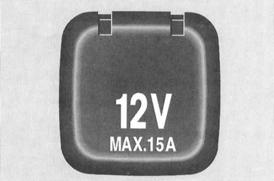
Power outlets are equipped with protective covers and are designed to connect additional equipment with a power consumption of not more than 180 W (12V x 15A)
Note. The sockets can be used even with the key removed from the ignition.
Interior lighting
Main saloon lights and front navigation lamps
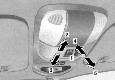
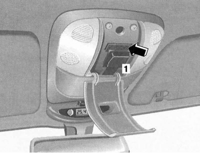
The interior light mode switch is located on the overhead console next to the sunroof power operation control switch, behind the control panel is the two-section main interior light assembly/garage door remote control holder.
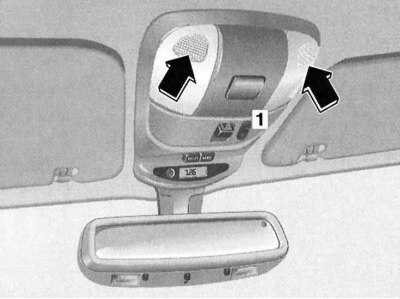
Location of the cabin lamp operation mode switch (1) and assembly design of a two-section main saloon lamp (arrows).
Activation / deactivation of each of the sections of the main saloon lamp is performed by pressing the corresponding lens. In addition, the lighting automatically turns on when the doors are unlocked from the remote control of a single lock, as well as when they are opened - closing the doors turns off the lamp with a certain time delay. The interior lighting is switched off automatically when the ignition is switched on.
A three-position key switch for the operation of the lamps allows you to turn on / off the rear salon lamps, activate the interior lighting mode when opening the doors, and completely turn off the interior lighting (switch neutral position).
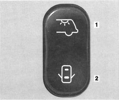
The principle of operation of the interior light switch (in the neutral position, the interior lighting remains off under all conditions)
1 - Turn on / off the rear interior lights
2 - Activation / deactivation of the interior lighting mode when opening the doors
Rear individual lamps (reading lamps)
Activation/deactivation of rear individual lights (reading lamps) produced by pressing the lenses of their shades. In addition, the lighting automatically turns on when the doors are opened - closing the doors turns off the lamp with a certain time delay. The interior lighting is switched off automatically when the ignition is switched on.
The rear individual lights are mounted in the headlining side sections directly behind the B-pillars.
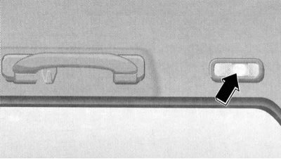
Luggage compartment light
The lantern is mounted in the central part of the rear section of the headliner and is equipped with an individual three-position switch that allows you to select the mode of operation of the luminaire.
Luggage compartment lamp assembly, lamp operation mode selection switch
1 - Off (the light stays off even when the tailgate is opened)
2 - On (the light stays on all the time)
3 - Door (The lamp is activated when the tailgate is opened)
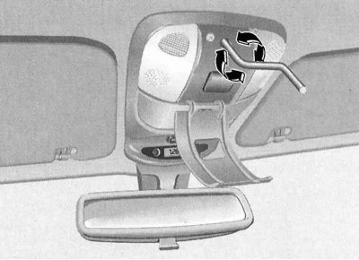
Garage door remote control
The holder for fixing the device is placed under the protective cover in the central part of the assembly of the two-section main saloon lamp.
Location of the holder for installation of the remote control of the garage door drive
General information
The built-in universal transceiver allows you to conveniently combine the functions of up to three individual hand-held remote controls and allows you to control the operation of most radio-frequency operating devices, such as a garage door opener, door lock actuators, security systems, etc. The transceiver is powered by an on-board battery, which eliminates the need for periodic battery replacement. The transceiver's memory is ROM-based, which means there is no need to re-enter data after disconnecting the battery.
Warning! The built-in universal transceiver is not intended for use with garage door openers that do not have an emergency stop reversing function. These requirements have been standardized for production units since April 1, 1982!
Programming the Universal Transceiver
Note. Once the programming code has been entered into the transceiver, the original transmitter should be retained in case re-programming is required (e.g. when buying a new car). When selling a car, the transceiver program code must be deleted from the device’s memory for security reasons. See below for details.
Attention! When entering the program code, the garage doors may start to open or close spontaneously - make sure that there are no people or pets in the doorway! Transceiver programming must be done with the engine off!
With the ignition off (key in position 1 or 2) press the left button of the transmitter on the overhead console of the car and, keeping it pressed, wait until the control LED mounted in the console just above the buttons starts flashing at a frequency of about 1 time per second.
Note. During the initial programming of any of the buttons, as well as when reprogramming after resetting the settings, the LED starts flashing almost immediately, when reprogramming a button already in use, the LED is activated only after about 20 seconds.
Without releasing the left button of the control panel, point the portable remote control from the standard configuration to the actuator, which will be controlled from this button, with the end equipped with a radiator to the left side of the saloon rear-view mirror, into which the antenna part of the transceiver is integrated and, without leaving the field of view control LED, press the control button of the portable remote control. Keep the button pressed until the blinking frequency of the control LED doubles, confirming that the information entered is correct.
Note. If the gate operating mechanism is equipped with a code change function (Rolling-Code), then you should synchronize the transceiver with the standard transmitter of the driven device, - see the instruction manual for the device.
The remaining two buttons on the control panel are programmed in a similar manner.
Rules for using a universal transceiver
After entering the appropriate program code, the transceiver can be used to control the corresponding actuator (e.g. controlling the operation of a garage door drive). To activate the device, simply press the appropriate button on the transceiver control panel (the key in the car ignition must be turned to position 1 or 2), - during the transmission of the control signal, the indicator light should work.
Note. The emitter functions with the button pressed continuously for 20 seconds, after which the command transmission process is interrupted, and the control LED switches to flashing mode - if necessary, press the control button again.
Diagnosis of program code input errors
If it is not possible to enter information from the handheld transmitter into the transceiver's memory quickly enough, proceed as follows:
- a) Replace the battery of the portable remote control;
- b) Make sure that the handheld remote control you bring to the transceiver is oriented correctly (the side with the battery compartment must be outside);
- c) Try to hold the simultaneously pressed buttons on both devices fairly securely;
- d) Make sure that the transmitter is at a distance of no more than 125 mm from the transceiver when entering information. If within 15 seconds the flashing frequency of the indicator light does not increase, confirming the success of entering the program code, try repeating the procedure by slightly changing the position of the transmitter relative to the transceiver - keep the indicator in sight at all times.
If you cannot enter the code under any circumstances, contact an authorized Mercedes-Benz workshop for advice.
Resetting the memory of the universal transceiver
The possibility of clearing the data entered for a separate button of the transceiver is not provided by the design of the device. To delete all the entered information, hold down the two side buttons on the transceiver control panel simultaneously for about 20 seconds. The buttons can be released as soon as the control LED starts flashing.
Note. It is recommended to clear the memory of the universal transmitter before selling the vehicle.
What to do in case of car theft
In the event of a car theft, the actuators of all transceiver-driven devices that are not equipped with a code interleaving function must be reprogrammed - if necessary, consult the representatives of the respective manufacturers.
When returning a stolen car, all buttons of the built-in transceiver should be reprogrammed.
Sun visors
The sun visors protect the eyes of the driver/front passenger from direct sunlight from both the front and the side.
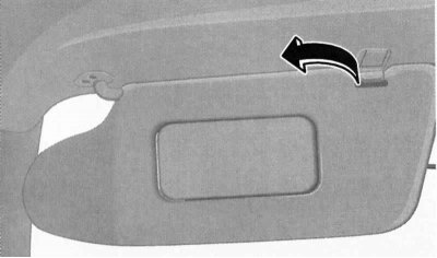
Sun visors have two working positions - to protect against side rays, release the visor from the retainer (arrow) and deploy it to the door glass (driver's visor shown).
On some models, a vanity mirror equipped with a hinged cover can be additionally equipped on the back of the sun visor. Opening the mirror cover with the ignition on (key in position 1 or 2) leads to the activation of the mirror illumination.
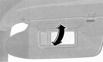
On some models, a vanity mirror equipped with a hinged cover and equipped with an illuminated vanity mirror can be installed on the back of the sun visor.
Glove boxes
The main glove box is equipped on the right side of the instrument panel and is equipped with a hinged lid with a rotary handle - opening the lid with the ignition on activates the illumination of the internal volume of the box.
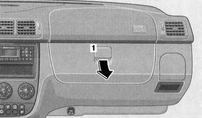
The hinged lid of the main glove box is equipped with a rotary handle (1)
An additional two-section storage box is equipped in the center console assembly, under the armrest between the front seats of the car. A coin box is provided in the lid of the console box.
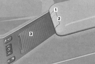
A two-section additional storage box is built into the console armrest
1 - Button for releasing the latch of the cover of the upper section of the console box
2 - Button for releasing the latch of the cover of the lower section of the console box
3 - Sliding access cover to the cup holder
Another lockable storage box is located under the front passenger seat assembly (see Section Access to the storage box of the right front seat).
Cup holders
Two folding cup holders are equipped on both sides of the instrument panel. To transfer the cup holder to the working position, it is enough to briefly press the assembly cover, then release it.
For converting the folding cup holder of the instrument panel (1) to the working position, briefly press its cover, then release it (driver's cup holder shown).
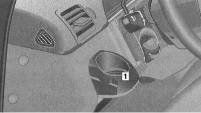
Another front cup holder is placed under the sliding cover in the front wall of the console armrest - slide the cover up and pulling the frame of the cup holder, move the latter to the working position.
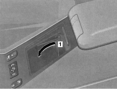
To move the front console cup holder to its working position, open the sliding cover, then pull the holder frame (1) in the direction of the arrow.
Another retractable two-section cup holder is equipped in the rear end wall of the center console. To transfer the cup holder to the working position, it is enough to briefly press the assembly cover, then release it.
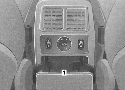
For transferring the retractable two-piece rear cup holder (1) to the working position, briefly press its cover, then release it.
Fire extinguisher
A regular place for attaching a fire extinguisher is equipped in the front of the cabin, next to the driver's seat. The fire extinguisher must be refilled after each use. The fire extinguisher should be checked every 1 - 2 years.
Attention! Carefully study the instructions for using the fire extinguisher installed in the car!
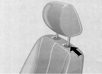
Removal and installation of head restraints
Front seat head restraints
To remove the head restraints, pull it all the way out of the guide channels of the seat back, then press the release button and completely release the guide rods of the assembly from the back.
To install, tuck the guide rods of the head restraint into the receiving grooves of the backrest (make sure assembly is oriented correctly) and lower the assembly down until the latch clicks into place.
A description of the procedure for adjusting the head restraints is given in Section Seat adjustment.
Rear bench seat head restraints
The procedure is the same as described above for the front head restraints.
To remove the head restraint raised to its highest position, press the release button.
Head restraints for folding seats in the third additional row
In the stowed position, the headrests of the folding seats tuck into the side wall of the seat cushion.
The procedure for removing and installing the head restraints on the backrests is similar to that described above for the front seats.
Top rack, ski holder
Fixation of the roof rack must be carried out exclusively on standard profile roof rails.
For transporting skis, use only special holders approved for use by Mercedes-Benz service centers.