
Valve springs
A special spring tester is required to properly check the condition of the valve springs. If it is not at your disposal, then you can make a simple comparison of the old and new valve springs. To do this, take the old and new valve springs and clamp them in a vise. Slowly compressing the vise jaws, observe the degree of compression of both springs. If they compress equally, then this indicates the good condition of the old spring. But if the working spring has a high compression ratio (looks shorter than new), then this is a clear sign of fatigue wear - such a spring should be replaced. Valve springs are replaced with a complete set.
The springs prepared for installation are exposed on a flat and smooth surface (on glass) so that tightly closed turns are at the bottom. A metal corner is placed on top of the springs and the gap between the upper coil of the spring and the plane of the corner is checked. This gap should not exceed 2.0 mm. Otherwise, the springs must be replaced.
Valve guides
Valve guides made of cast iron have different diameters for intake and exhaust valves. Exhaust valve guides have a larger bore and are shorter, making them easy to sort. Pulling a rag soaked in gasoline through the bushings, clean the bushings. Valve stems are best cleaned with a rotating metal brush attached to an electric drill.
Wear control of the guide bushings is carried out using a calibrated mandrel. If the rejection gauge of the mandrel freely enters the guide bushing, then such a bushing should be replaced with a new one. To dismantle the bushings, use a special mandrel with a ledge. If it is possible to use guide bushings of the 1st standard size, then a special mandrel is used for their installation, with which the guide bushing is pressed into the seat until the retaining ring enters the groove on the cylinder head. When installing guide bushings of repair size groups, the mounting sockets must be pre-treated with manual broaching reamers. Since the guide bushings must be cooled with dry ice before being pressed in, we recommend that the cylinder head be sent to a workshop for the installation of new guide bushings.
Before replacing the valve guides, first check the general condition of the cylinder head. After pressing in, the bushings are bored to the required dimensions: 8.00–8.015 mm for intake valves and 9.00–9.015 for exhaust valves. Exhaust valve guides are long.
When replacing the guide bushings, the valves must also be replaced, and the valve seats must be ground.
Note. Grinding of valve seats is carried out only after replacing the valve guides. If it suddenly turns out that the saddles can no longer be bored, then the guide bushings should not be changed.
Valve seats
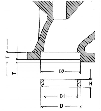
Pic. 37. Main dimensions of valve seats: D is the outer diameter of the valve seat; D1 is the inner diameter of the valve seat; D2 - seat for the valve seat in the cylinder head; H is the height of the valve seat; T is the distance between the plane of the cylinder head and the upper edge of the valve seat; H=6.97-7.00 mm - for all valves; T \u003d 2.37-2.25 mm - for intake valves; T = 2.44-2.25 mm - for exhaust valves
If the camshaft bearings are badly worn, then there is no need to bore the valve seats, but the cylinder head assembly should be replaced. Valve seats are checked for wear or pitting. Light wear can be removed by milling with a 45 degree taper cutter. If the valve seat has become very wide due to high wear, then such seats must be replaced. Valve seats are pressed into the cylinder head, and it is best to remove them by drilling or unscrewing with the help of special borings. When doing this, be very careful not to damage the cylinder head. Measure the diameter of the base hole D1 (pic. 37) and, if necessary, bore to the next repair size. Valve seats with repair allowances may be rebored until the prescribed overlap of 0.068-0.10 mm is achieved. The intake valve seats are larger.
Heat the cylinder head in a water bath to 90°C, and cool the valve seat on dry ice, after which it can be pressed into the seat with a special mandrel. This operation is recommended to be carried out at the service station.
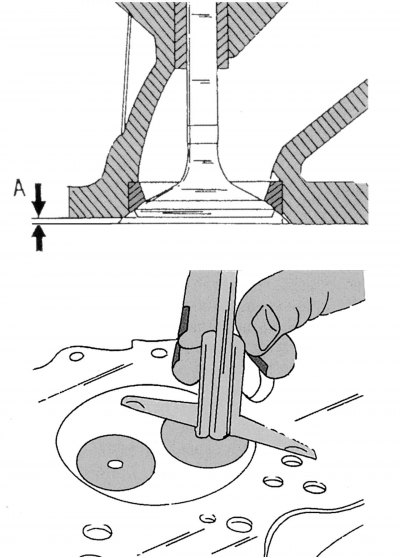
Pic. 38. Determination of size A
Finish the valve seat with a suitable countersink and grinding wheel on a valve grinder. Using the valve, measure the maximum distance A as shown at the bottom of fig. 38. When installing a new valve and valve seat, distance A should be 0.1–0.5 mm. The wear limit is 1.0 mm.
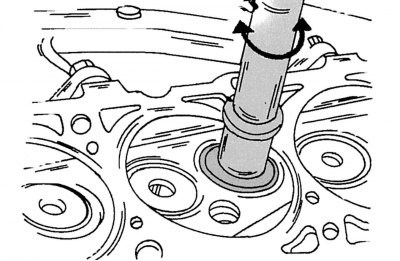
Pic. 39. Lapping valves to seats
After machining, measure the width of the valve seat sealing band. If the width of the sealing belt of the inlet valve seat differs from 2.5 mm, and the exhaust valve seats - from the value of 3.5 mm, then such seats must be processed with a 15-degree cutter in the upper part and a 60-degree cutter in the lower part. Milling stops as soon as the width of the sealing belt of the valve seat enters the above limits. After milling, the valve seats must be lapped. To do this, a small amount of grinding paste is applied to the valve seat. A suction cup is attached to the top of the valve head, with the help of which rotational movements are communicated to the valve in one direction or the other (pic. 39). From time to time it is necessary to turn the valve a quarter of a turn, and then rub again with rotational movements. If necessary, add grinding paste to the valve seat. After lapping, remove the remaining paste from the valve and seat and check the fit of the valve on the seat and head. On both parts, the resulting matte belt should be clearly visible, which determines the width of the sealing belt of the valve seat.
With a pencil, apply a few dashes on the resulting matte belt with an interval of 1 mm along its perimeter. Then lower the valve into the seat and rotate it 90°around the stem, pressing the valve lightly against the seat.
Remove the valve from the seat and check that the pencil marks have disappeared. If the width of the sealing belts of the valve seats is within the prescribed limits, then the cylinder head can be installed on the engine. Otherwise, it is necessary to continue processing and lapping the seats or replace the cylinder head.
Valves
Due to the use of hydraulic valve clearance compensators, the valve stem ends of the intake and exhaust valves are specially machined to withstand increased stress. Minor damage to the valve heads can be repaired by lapping them against the seats as described above. More serious damage to the sealing surfaces can be repaired with a valve grinder. On polished valves, the thickness of the edges of their plates should not be less than 0.5–0.7 mm for intake valves and 0.5–0.6 mm for exhaust valves.
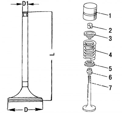
Pic. 40. The main dimensions of the valves: D - plate diameter (heads) valve; D1 is the diameter of the valve stem; L is the length of the valve; 1 - pusher; 2 - conical crackers; 3 - valve spring plate; 4 - valve spring; 5 - lower support plate of the valve spring; 6 - oil cap; 7 - valve
These types of engines use valves without sodium filling, as was the case on other types of Mercedes-Benz engines. On fig. 40 shows the dimensions of the valves. Valves whose dimensions do not correspond to the specified dimensions must be replaced with new ones.
When placing an order for valves, always indicate their purpose (inlet or outlet), and also that these valves are designed for a diesel engine.
In some cases, only the exhaust valves can be replaced if, for example, they have burnt edges.
Cylinder head
Thoroughly clean the mating surfaces of the cylinder head and cylinder block, and then check the cylinder head for deformation. For this purpose, place a ruler on the mating surface of the cylinder head and use a feeler gauge to measure the gap under the ruler in the longitudinal, transverse and diagonal directions. If during the measurement the gap between the ruler and the surface of the cylinder head in the longitudinal direction exceeds 0.10 mm, then this cylinder head should be sent to a specialized service station. When installing the ruler in the transverse direction of the cylinder head, there should be no gap under the ruler. Cylinder heads can be ground as long as the corresponding adjustment of the valve height allows this (size A in fig. 38).
In the same way, it is necessary to check the height of the protruding part of the prechambers for diesel fuel injection (601st engine). The edge of the prechambers should protrude by 7.6–8.1 mm.
At the service station, the prescribed size of the protruding part of the prechambers can be set using a set of sealing gaskets of various thicknesses installed under the prechambers. This work must necessarily be carried out at the service station, since this requires a special tool for pressing out and pressing in the prechambers.
Camshaft
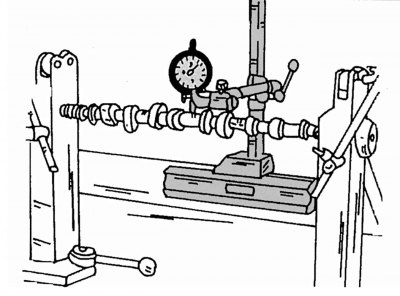
Pic. 41. Checking the deformation of the camshaft
The following text describes the work involved in checking and monitoring the condition of the camshaft. Structural description of the camshaft, see Sec. 2.12.6. Install the camshaft on prisms placed under the outer bearing journals, or clamp it between the centers of the lathe, as shown in Fig. 41, and bring the probe of the measuring indicator to the middle support neck. Then, slowly turning the camshaft, it is necessary to follow the indications of the arrow. If the arrow deviates beyond a division of 0.01 mm, then this will mean that the shaft is deformed and must be replaced.
Replacement of oil seals (cylinder head mounted on the engine)
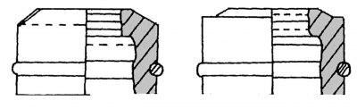
Pic. 42. Shape of valve stem caps: on the left - for graduation; right - for intake valves
Oil seals can be found in the repair kit. The repair kit includes protective sleeves that are put on the intake valve stems during installation. Valve stem seals for intake and exhaust valves differ from each other both in their diameters and in shape, so it is impossible to confuse them (pic. 42).
A special tool is usually used to install the caps. If it is not at hand, then you can use a thin tube, but be very careful not to damage the sealing cuffs and the coupling springs of the caps. When installing oil caps on the valve stems, crackers and valve springs must be removed from the latter. To prevent the valve from falling into the cylinder, it is necessary that the piston of this cylinder be at TDC. On four-cylinder engines, this operation is greatly facilitated by the fact that each time two pistons are at TDC. On five-cylinder engines, this work is a little more difficult, since each time it is necessary to turn the engine crankshaft at a certain angle, setting the piston of the next cylinder to TDC. Replacement of oil seals must be carried out as follows (We recommend entrusting this work to an experienced specialist).
Crank the engine until the piston of the first cylinder is at TDC.
Dismantle the camshaft (subsection 2.12.6).
Remove the valve cotters of the first cylinder as described in subsection 2.4.2. On a four-cylinder engine, you can simultaneously remove crackers and remove the valve springs from the valves of the fourth cylinder.
Carefully, so as not to damage the valve stems and tappet holes, pull off the old oil seals with tongs.
Lubricate the new valve stem seals with oil and carefully push them down over the valve stems. Don't forget to put protective sleeves on the intake valve stems. Fit the valve stem seals firmly onto the valve guides.
Install the valve springs, color-coded down, and install the valve cotters, making sure that the cotters are well seated in the grooves and conical recesses of the upper valve spring support plates.
Raise the camshaft drive sprocket slightly so that the chain does not disengage, and rotate the crankshaft of the four-cylinder engine a half turn. After that, you can similarly change the valve stem seals on the valves of the second and third cylinders. When working on a five-cylinder engine, the crankshaft must be rotated until the piston of the next cylinder reaches TDC. Alternation of subsequent cylinders, the piston of which passes TDC: 2–4–5–3. As noted above, this work requires special care.
Note. The valve spring compressor must be clamped very slowly, as some valve cotters get stuck in the grooves. Avoid situations where, due to the rapid clamping of the device, the valve rests with its plate against the piston. The tool should only act on the valve spring, compressing and moving it down.