
Valve springs must be checked on a special stand. In the absence of a stand, you can check the spring by comparing it with a new spring. To do this, the springs must be placed side by side and between them put a tie rod with two supporting surfaces, if the springs deform in the same way when compressed, then the old spring is suitable for further operation. If the old spring is shorter than the new one, it is a sign of fatigue and should be replaced.
Arrange the springs in a row on a flat surface, put a metal square on top, the maximum gap between the upper ends of the springs and the surface of the square should not exceed 2 mm.
As already mentioned, various springs are installed on these engines. Internal and external valve springs differ in size and characteristics. The spring sizes are shown in the respective tables. It is not allowed to install springs of other sizes.
When changing the working length of the spring (e.g. when machining a valve seat) it is possible to restore it by installing new spring plates.
Valve guides
- Clean guide bushings with petrol. Clean the protruding parts of the guide bushings with a wire brush clamped in the chuck of an electric drill.
- Check the wear of the valve guides using a gauge, as shown in fig. 24. If the non-going side of the gauge fits into the guide bore, the valve guide must be replaced.
Pic. 24. Checking the valve guide with a gauge.
The valve guide is pressed out using a mandrel installed on the side of the combustion chamber. It is possible to install a valve guide of nominal size 1, which is pressed into the cylinder head with a mandrel until the adjusting ring stops against the end surface of the head. Oversized valve guide can be installed (marked in red), the hole is then machined by manual reamer. Before installation, a new guide bush is recommended to be cooled in dry ice, and if not. then heat the cylinder head in hot water to 80°C and insert the valve guide. Check the general condition of the cylinder head before replacing the valve guide. After pressing the valve guide sleeve, the hole must be reamed to a size of 9.000...9.015 mm.
When replacing a valve guide, a new valve must be installed.
Caution: After replacing the valve guide, the valve seat must be countersinked. If machining of the valve seat is no longer possible, do not change the valve guide (see below).
Valve seats
Check for wear or damage to valve seat surfaces. Minor wear is eliminated by countersinking at an angle of 45°. If this repair is no longer possible, the valve seat must be replaced.
The valve seats are pressed into the cylinder head and their dimensions are different for different types of engines. To remove the old rings, they are drilled and, after destruction, are removed from the socket in the cylinder head. Then check the size of the hole "D1" (pic. 25) and, if necessary, processed to the next repair size. The valve seat of the repair size should provide an interference fit of 0.074... 0.1 mm. The valve seat diameters for different types of engines are different.
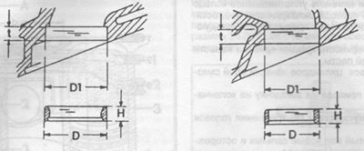
Pic. 25. Inlet and outlet valve seat dimensions.
Heat the cylinder head in a water bath to 90°C, and cool the valve seat with dry ice, then press the valve seat into the cylinder head using a mandrel. In the absence of the necessary conditions, you need to contact the repair shop.
After machining, measure the width of the chamfer of the valve seat. It should be 1.3... 2.0 mm for the inlet valve and 1.5... 2.0 mm for the outlet. If necessary, the width of the working chamfer is brought to the above dimensions by countersinking from above with a countersink at an angle of 15°and from below by a countersink at an angle of 60°. Then it is necessary to grind the working chamfers of the valve seat and the valve using lapping paste. Apply the paste on the working chamfer of the valve seat and install the valve, use the suction cup to rotate the valve in two directions, pressing it against the surface of the seat. After lapping, clean the parts of dirt and lapping paste residues and check the working chamfers of the valve seat and valve. On both parts, a continuous opaque ring should be clearly visible, corresponding to the width of the working chamfer of the valve seat.
Use a lead rod to put a strip on the working chamfer of the valve, then carefully insert the valve into the guide sleeve and, pressing against the valve seat, turn the valve 90°.
Remove the valve from the guide sleeve and check the working chamfer of the valve seat, if the traces of the lead rod are evenly distributed over the entire surface of the working chamfer, this means that the grinding is done correctly and the cylinder head is suitable for further operation. If there are gaps, repeat the grinding or use a replacement cylinder head.
Valve
Minor damage to the valve face is repaired by lapping against the valve seat as described above.
Measure the valves for compliance with the dimensions given in the tables. If the dimensions are not correct, the valve must be replaced, paying attention to the following:
The exhaust valve stem is filled with sodium. Therefore, during disposal, certain safety rules must be observed. Due to the danger of explosion, sodium-filled valves must not be sent for remelting or tooling (for example, punch) before sodium removal. When removing sodium from the valve, it must be taken into account that sodium reacts very actively with water and aqueous solutions with the release of hydrogen, which can lead to a fire. You can neutralize sodium in a solution of 2 liters of alcohol and 1 liter of water in a container located in an open area.
When ordering, please specify that the valves are required for 116 series vehicles. The series number is stamped on the end of the valve stem.
Cylinder head
Carefully clean the mating surfaces of the cylinder head and cylinder block and check that the split surface of the cylinder head is not warped. To do this, put a measuring parallel on the plane and measure the height of the gap between the parallel and the plane of the head with a probe, measure it in the longitudinal, transverse and diagonal directions. If the flatness does not exceed 0.08 mm, then the head can be ground on the marking plate. If the gap is larger in several places, then the cylinder head must be replaced.
The split surface of the cylinder head can be ground, however, a certain dimension must be maintained between the split surface and the upper surface of the head, so this work is preferably done at a Mercedes service station. After grinding the split surface, the valve seats must be seated deeper. To check the valve is inserted into the seat and the distance between the ends of the valve stems and the split surface of the cylinder head is measured. The required size is achieved by countersinking the working chamfer of the valve seat.
Camshaft
The camshaft is placed with extreme supports on a measuring prism or fixed in measuring centers and, using a dial indicator, check the runout of the middle bearing journals by slowly rotating the camshaft. If the runout exceeds 0.03 mm, then the shaft is rejected and must be replaced. The support necks can be ground twice. Information about this work can be obtained from the service station.