



Use a feeler gauge to measure the gaps between the piston rings and the corresponding piston grooves, compare the results with the data in the tables. Increased gaps indicate wear of either the piston ring or the piston.
Install the ring in the lower cylinder belt at a distance of 20 mm from the lower edge and measure the gap in the piston ring lock with a feeler gauge. For engines of both series, these values are different and are given in the corresponding tables.
With a small gap (for example, when using new rings) it can be brought to the required size by filing the ends of the lock. If the gap is increased, the ring must be replaced.
Check the piston pins and the upper heads of the connecting rods for wear and damage. If one of the connecting rods is defective, it can be replaced separately, taking into account that the difference in the weight of the connecting rods of this engine should not exceed 4 g. The connecting rods of the 117 series engines are longer.
When reusing connecting rod cap bolts, measure the bolt diameter at the narrow end with a caliper (see fig. 29). If the size is less than 8.0 mm, the bolt must be replaced as described below. Before replacing, one check must be made. Place the connecting rod lower head cover on the mounting bolt and rotate it 180° relative to the connecting rod. Place the connecting rod and cover horizontally, as shown in Fig. 30. If the cover falls down under its own weight, the bolt must be replaced. To replace the bolts, do the following:
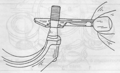
Fig. 29. Measuring the connecting rod cap bolt shaft.
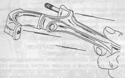
Fig. 30. Checking the connecting rod cap mounting bolts.
Press out the old bolts from the lower connecting rod head.
Place the connecting rod with the split surface on a steel plate with a hole larger than the diameter of the bolt and press in new mounting bolts one by one.
Using a device, check the connecting rod for twisting and bending.
Place the cover on the connecting rod and tighten the fastening nuts to a torque of 40...50 Nm.
Place the connecting rod assembly in a vice and measure the diameter of the lower head with a bore gauge, as shown in Fig. 31. If the size exceeds 55.62 mm or the hole is found to be out of round, the surface of the connecting rod cap can be lapped on a marking plate; the layer of metal removed should not exceed 0.02 mm.
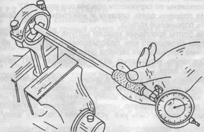
Fig. 31. Measuring the hole in the lower head of the connecting rod with a bore gauge.
If the bushing in the upper connecting rod head is damaged or changes in size, it can be pressed out and a new bushing can be pressed in. The bushing is expanded to a size of 26.007...26.013 mm, which provides the required clearance between the pin and the upper connecting rod head.
Measuring clearances in connecting rod bearings
These works are carried out in conjunction with measuring the clearances in the main bearings (section 2.7.2).
Publication reprinted from this resource [Mercedesman.ru]