
When replacing connecting rods, check that they comply with the weight tolerances.
Prepare a mandrel for installing the piston pins.
Lubricate the piston pins, and connect the piston and connecting rod with hand pressure. Do not heat the piston. The arrow on the piston head must point in the direction of travel, and the grooves on the connecting rod bearings must be located on the outside of the engine, as shown in Fig. 32.
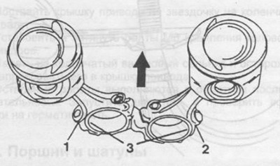
Pic. 32. Pistons and connecting rods assy. The arrow shows the direction of movement.
1 - connecting rod,
2 - connecting rod cover,
3 - groove.
Insert retaining rings into the piston bosses on both sides and check their position in the grooves.
Check piston rotation relative to connecting rod.
Using pliers, install the piston rings into the piston grooves, paying special attention to the position of the two upper compression rings (see fig. 27).
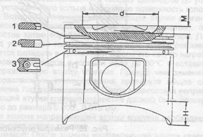
Pic. 27. Piston section.
1 - top compression ring,
2 - lower compression ring,
3 - oil scraper ring with spring, d=52 mm (350 SE), d=66 mm (450 SE), M=1 mm (350 SE), M=5.9mm (450 SE),
H is the place where the piston diameter is measured.