
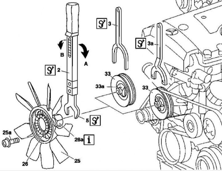
Viscous Clutch Fan Impeller Installation Details on 111 Series Gasoline Models (ML 230)
2 - Torque wrench; 3 - Holder (version 1); 3a - Holder (version 2); 5 - Open-end wrench; 33 - Drive belt pulley; 33a - Retainer
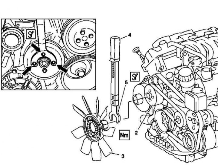
Installation details of the viscous clutch fan impeller on models with 112/113 series gasoline engines
1 - Holder (version 1); 2 - Drive belt pulley; 3 - Assembly of the impeller with a viscous coupling; 4 - Torque wrench; 5 - open end wrench
Details of the installation of the impeller of a fan with a viscous coupling on the example of gasoline models are shown in the illustrations.
Fan shroud
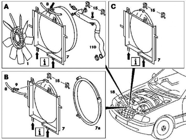
Viscous Fan Shroud Installation Details (on the example of the ML 230 models)
1 - Assembling the impeller with a viscous coupling; 7 - Casing of the fan assembly; 7a - casing rim; 8 - Hose of the cooling path; 15 - Spring clamps; 18 - Radiator of the cooling system; 110 - Air boost path sleeve (with appropriate equipment)
Details of the installation of the fan shroud with a viscous coupling on the example of gasoline models equipped with a 111 series engine are shown in the illustrations.
Electric fan
M612
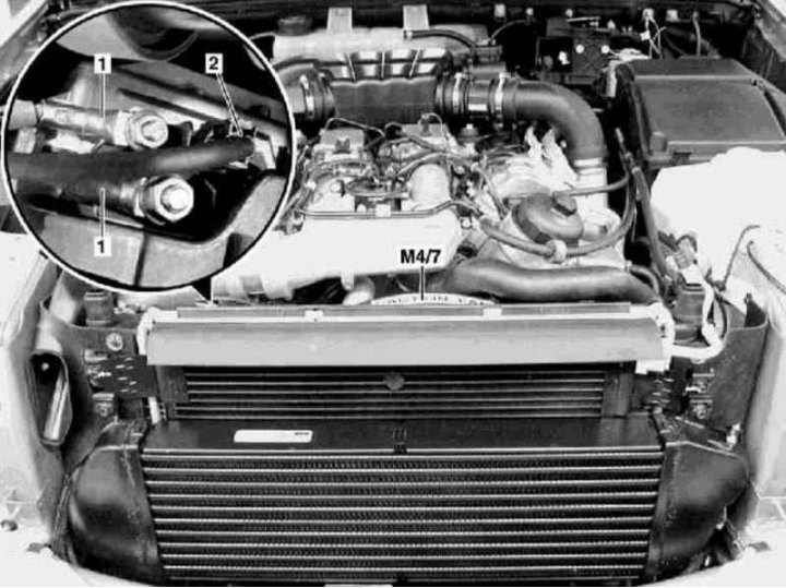
Electric fan assembly installation details on ML 270 CDI models
1 - Contact connector for electrical wiring of the clutch; 2 - Wiring circuit 30; 3 - Clamps; 4 - Locking nuts; 5 - Bolts; М4/7 - Fan drive motor
1. Installation details of the electric fan assembly using the example of the ML 270 CDI model are presented in the illustration, to which all references in the text refer.
2. Drive the car onto the lift.
3. Open the hood.
4. Disconnect the negative cable from the battery.
5. Disconnect the connector (1) clutch wiring.
6. Disconnect circuit 30 wiring from fan (2).
7. Release the electrical wiring from the support bracket.
8. Remove the front soundproofing section.
9. Release the lower latches (3) fan assembly mountings.
10. Turn out bolts (5).
11. Remove lock nuts (4).
12. Remove the fan assembly from the hinged supports at the top edge of the radiator and, lowering it down, remove it from the engine compartment.
13. Installation is carried out in the reverse order.
M628
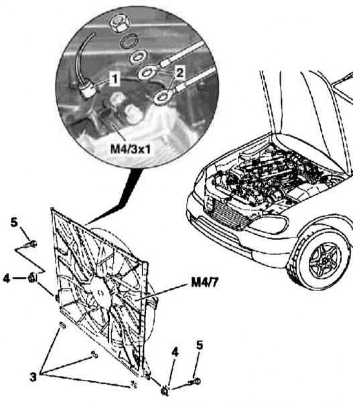
Electric fan assembly installation details on ML 400 CDI models
1 - Circuit 30 power supply; 2 - Contact connector for electrical wiring; М4/7 - Fan drive motor
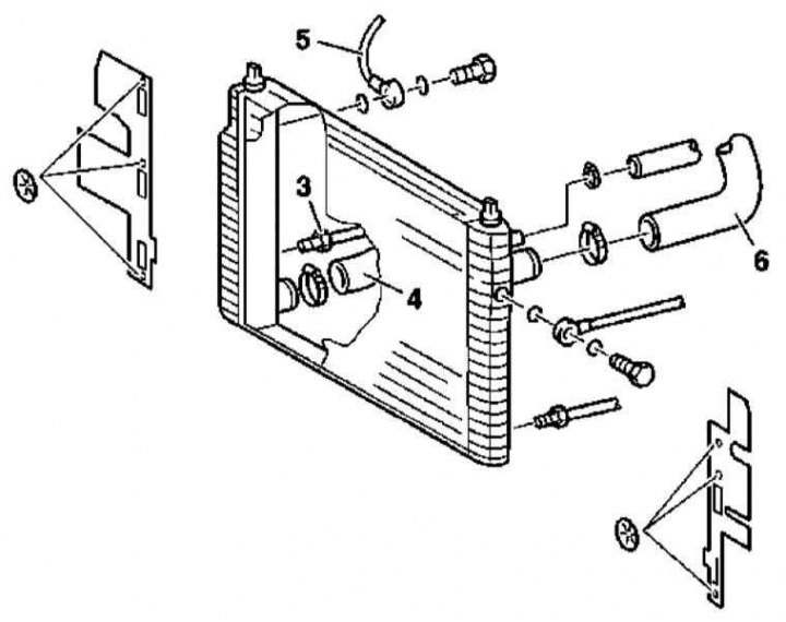
Electric fan assembly installation details on ML 400 CDI models
3 - Lower oil pipeline; 4 - Lower hose of the cooling path; 5 - Upper oil pipeline; 6 - Upper hose of the cooling path
1. Illustrative material for removing and installing the electric fan assembly on ML 400 CDI models is presented in illustrations, which include all references in the text.
2. Drive the car onto the lift.
3. Open the hood.
4. Disconnect the negative cable from the battery.
5. Disconnect the lower line of the ATF cooling path from the radiator (3).
6. Release the lower fan assembly retainers.
7. Turn out the bottom lateral bolts of fastening of fan assembly.
8. Disconnect the electrical wiring connector (2).
9. Release the electrical wiring from the support bracket.
10. Disconnect the upper hose of the cooling path from the radiator (6) and upper oil line (5).
11. Lift up and remove the fan assembly from the engine compartment.
12. Installation is carried out in the reverse order.