
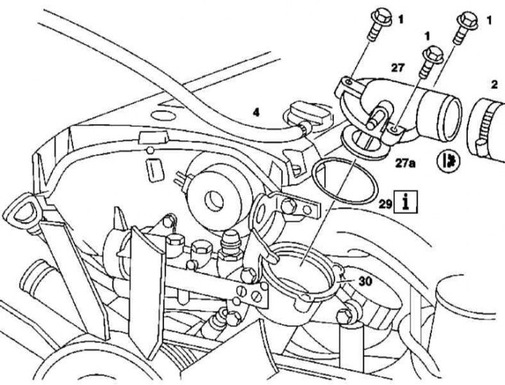
111 Series Engine Thermostat Operating Element Installation Details
1. Installation details of the 111 series engine thermostat operating element are shown in the illustration, to which all references in the text refer.
2. Empty the cooling system (see chapter Checking the cooling system and frost resistance of the coolant, changing the fluid).
3. Remove the top front cover.
4. Disconnect the coolant hoses (2 and 4).
5. Turn out fixing bolts (1) and remove the cover (27) thermostat with a built-in working element (27a) from the thermostat housing (30).
Attention! To avoid irreversible damage, the operating element must not be removed from the cover! In case of need replacement of an element is made in assembly with a cover.
6. Installation is carried out in the reverse order.
7. Finally, check the cooling system for signs of leaks.
Thermostat assembly with casing
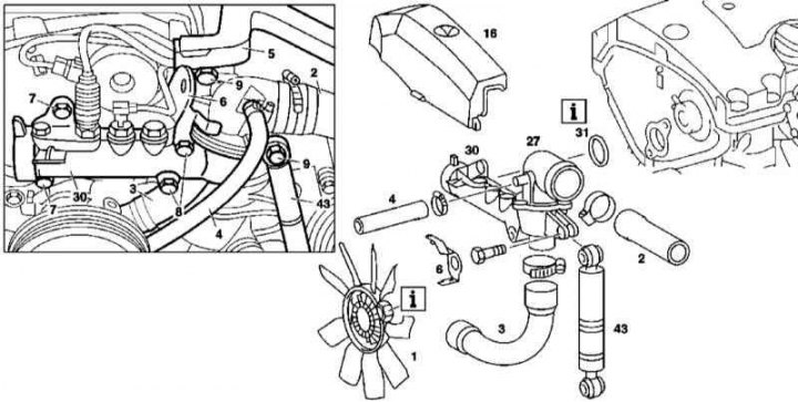
111 Series Engine Thermostat Assembly Installation Details
1. Installation details of the 111 series engine thermostat assembly are shown in the illustration, to which all references in the text refer.
2. Remove the viscous cooling fan assembly (1).
3. Empty the cooling system (see chapter Checking the cooling system and frost resistance of the coolant, changing the fluid).
4. Remove power unit cover (16).
5. Disconnect the coolant hoses (2, 3 and 4).
6. Disconnect the electrical wiring and vacuum lines from the thermostat mounted in the casing (30) temperature sensor.
7. Remove eyelet (6).
8. Turn out fixing bolts (7, 8 and 9) and remove the thermostat cover (30) complete with lid (27).
9. Thoroughly clean the sealing surface, prepare a replacement sealing ring (31).
10. If the thermostat housing needs to be replaced, remove the temperature sensor from it.
11. Installation is carried out in the reverse order.
12. Finally, check the cooling system for signs of leaks.
M112/113
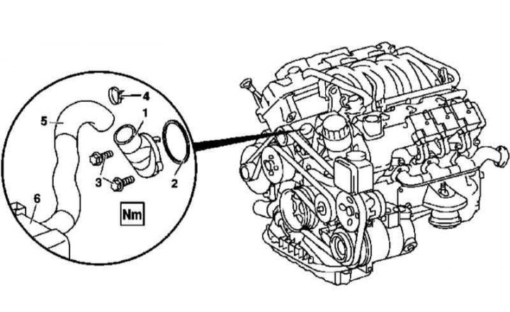
112 and 113 Series Engine Thermostat Assembly Installation Parts
1 - Thermostat casing; 2 - O-ring; 3 - Mounting bolts; 4 - Clamp; 5 - Hose of the cooling path; 6 - Radiator
1. Details of the installation of the thermostat of engines of the 112 and 113 series are shown in the illustration, to which all references in the text refer.
2. Empty the cooling system (see chapter Checking the cooling system and frost resistance of the coolant, changing the fluid).
3. Remove the powertrain trim panel/air cleaner assembly.
4. Disconnect the coolant hose (5).
5. Turn out fixing bolts (3) and remove the thermostat cover (1) assembled with a working element.
Attention! To avoid irreversible damage, the operating element must not be removed from the cover! In case of need replacement of an element is made in assembly with a cover.
6. Installation is carried out in the reverse order.
7. Finally, check the cooling system for signs of leaks.
Diesel models
M612
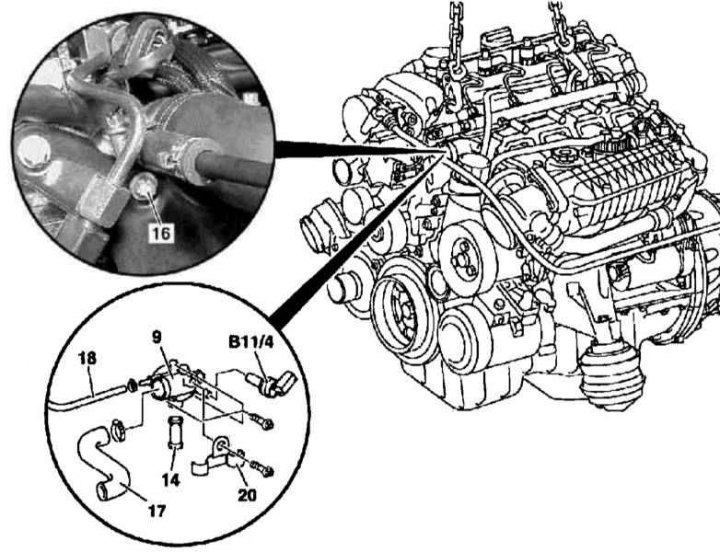
612 Series Engine Thermostat Installation Details
9 - Thermostat casing; 14 - Fitting; 16 - Bolt; 17 - Hose of the cooling path; 18 - Ventilation hose; 20 - Support bracket for fuel lines; B11 / 4 - Coolant temperature sensor
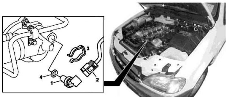
Installation details of the coolant temperature sensor on the 612 series engine
1 - Coolant temperature sensor; 2 - Contact connector for electrical wiring; 3 - Retainer; 4 - O-ring
1. Installation details of the 612 series engine thermostat and coolant temperature sensor are shown in the illustrations, which include all references in the text.
2. Empty the cooling system (see chapter Checking the cooling system and frost resistance of the coolant, changing the fluid).
3. Remove panels of finishing of a cover of a head of cylinders.
4. Disconnect the electrical wiring from the coolant temperature sensor (B11/4).
5. If necessary, remove the retainer (3) and remove the sensor (1), - prepare a new O-ring (4).
6. Remove fuel lines support bracket (20). Disconnect from thermostat housing (9) cooling lines (17) and ventilation (18) paths.
7. Remove the thermostat cover (9), - pay attention to the installation position of the connecting fitting (14), prepare a new gasket.
8. Installation is carried out in the reverse order.
9. Finally, check the cooling system for signs of leaks.
M628
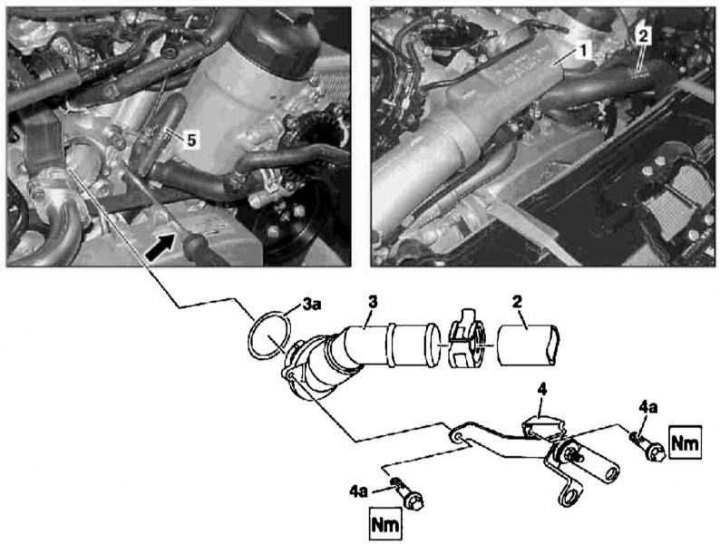
628 Series Engine Thermostat Installation Details
1 - Upper air duct; 2 - Hose of the cooling path; 3 - Thermostat casing; 3a - O-ring; 4 - Air duct support bracket (not applicable); 4a - Screws; 5 - Coolant hose
1. Installation details of the 628 engine thermostat are shown in the illustration, to which all references in the text refer.
2. Remove the bypass sleeve of the air boost path.
3. Disconnect from the thermostat housing (3) coolant hose (2).
4. Remove the thermostat cover (3) assembled with the working element, - prepare a replacement sealing ring (3a).
5. Installation is carried out in the reverse order.
6. Finally, check the cooling system for signs of leaks.