
Petrol models
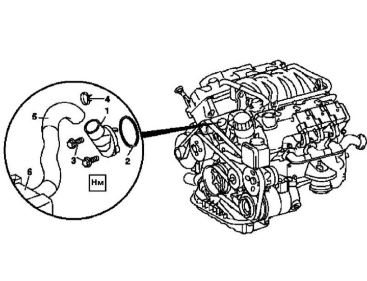
Installation details of the thermostat assembly on gasoline engines
1 - Thermostat casing; 2 - O-ring; 3 - Mounting bolts; 4 - Clamp; 5 - Hose of the cooling path; 6 - Radiator
1. Empty the cooling system (see chapter Ongoing care and maintenance).
2. Remove the powertrain trim panel/air cleaner assembly.
3. Disconnect the coolant hose (5).
4. Turn out fixing bolts (3) and remove the thermostat cover (1) assembled with a working element.
Attention! In order to avoid irreversible damage, the working element should not be removed from the cover - if necessary, the replacement of the element is carried out in assembly with the latter!
5. Installation is carried out in the reverse order. Don't forget to replace the o-ring (2), make sure that the fasteners are tightened to the required torque.
6. Finally, check the cooling system for signs of leaks.
Diesel models
M612
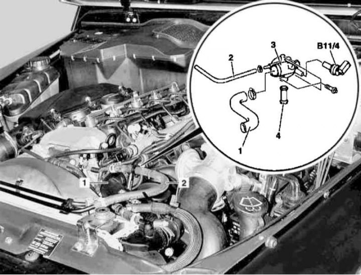
Installing the Thermostat and Coolant Temperature Sensor on a 612 Series Diesel Engine
1 - Hose of the cooling path; 2 - Ventilation hose; 3 - Thermostat casing; 4 - Connecting fitting; B11 / 4 - Coolant temperature sensor
1. Remove the crankcase protection.
2. Empty the cooling system (see chapter Ongoing care and maintenance).
3. Remove panels of finishing of a cover of a head of cylinders.
4. Disconnect the electrical wiring from the coolant temperature sensor (B11/4).
5. Disconnect from the thermostat housing (3) cooling lines (1) and ventilation (2) paths, - check the condition of the mounting clamps, if necessary, prepare a replacement.
6. Remove the thermostat cover (3), - pay attention to the installation position of the connecting fitting (4), prepare a new gasket.
7. Installation is carried out in the reverse order.
8. Finally, check the cooling system for signs of leaks.
M628
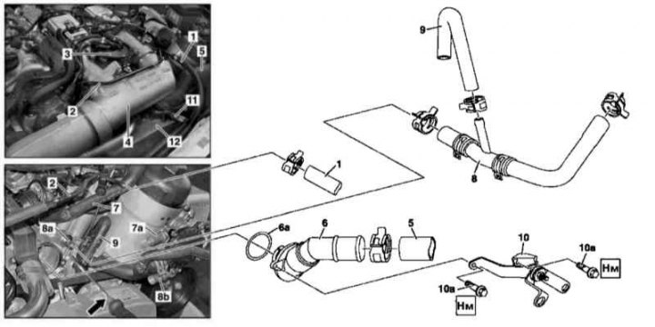
Thermostat Installation Details on 628 Series Diesel Engine
1 - Coolant hose (ventilation); 2 - Ventilation line; 3 - Fuel filter; 4 - Upper air duct; 5 - Hose of the cooling path; 6 - Thermostat casing; 6a - O-ring; 7 - Hose of the cooling path; 7a - Connecting fitting on the oil filter housing; 8 - Line of the cooling path; 8a - Connecting fitting on the crankcase; 8b - Connecting fitting on the oil filter housing; 9 - Hose of the cooling path; 10 - Support bracket for charge air cooler; 10a - Bolts; 11 - Hose of the cooling path; 12 - Charge air cooler
1. Jack up the car and put it on stands.
2. Empty the cooling system (see chapter Ongoing care and maintenance).
3. Remove the air cleaner.
4. Remove the cooling fan shroud (see Section Removing and installing the cooling fan assembly).
5. Install the air conditioning radiator/condenser shield (400x680x1 mm metal or plastic plate fitted with a suitable support bracket).
6. Remove fuel filter (3) (see chapter Ongoing care and maintenance), - when installing the filter, it will be reasonable to replace it.
7. Disconnect from vent line (2) coolant hose (1), - check the condition of the mounting clamp, prepare a replacement if necessary.
8. Disconnect the coolant hose (11) from charge air cooler (12), - check the condition of the mounting clamp, prepare a replacement if necessary.
9. Remove the throttle actuator assembly with the upper air duct (4).
10. Disconnect from the thermostat housing (6) coolant hose (5), - check the condition of the mounting clamp, prepare a replacement if necessary.
11. Disconnect the coolant hose (7) from fitting (7a) control valve of the crankcase ventilation system, - check the condition of the mounting clamp, if necessary, prepare a replacement.
12. Disconnecting from fittings (8a and 8b) and hose (9), remove the coolant line (8).
13. Remove the support bracket (10) charge air cooler, - in order to provide access to the mounting bolt (10a) pry with a screwdriver (arrow) and push aside the hose (9).
14. Remove the thermostat cover (6) assembled with a working element.
15. Installation is carried out in the reverse order.
16. Finally, check the cooling system for signs of leak development.