



Contents: Petrol models ↡ Diesel models ↡
Petrol models
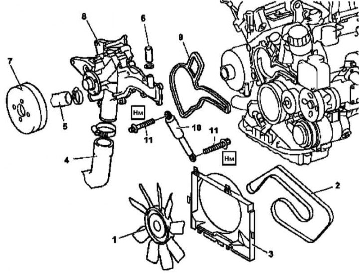
Water pump installation details for petrol models
1 - Assembly of the impeller with a viscous coupling; 2 - Auxiliary drive belt; 3 - Fan assembly casing; 4, 5 - Cooling tract hoses; 6 - Cooling tract hose connected to liquid cooler oil filter heat exchanger; 7 - Water pump drive pulley; 8 - Pump assembly; 9 - Sealing gasket; 10 - Vibration damper (not used on the models under consideration); 11 - Bolts
1. Remove the engine trim panel/air cleaner.
2. Remove the fan assembly (see Section Removal and installation the cooling system fan assembly).
3. Drain the coolant from the radiator (see Chapter Routine care and maintenance).
4. Remove the accessory drive belt (2) (see Chapter Engine).
5. Remove the accessory drive belt tensioner (see Chapter Engine).
6. Remove the cooling tract hoses (4 and 5) - check the condition of the fastening clamps. Prepare a replacement if necessary.
7. Disconnect the hose (6) from the liquid heat exchanger of the engine lubrication system - if necessary, prepare a replacement clamp.
8. Remove the water pump drive pulley (7).
Publication reprinted from this resource: mercedesman
9. Unscrew the mounting bolts and remove the pump assembly (8).
10. Installation is carried out in the reverse order - do not forget to replace the sealing gasket (9).
11. Finally, check the cooling system for signs of developing leaks.
Diesel models
M612
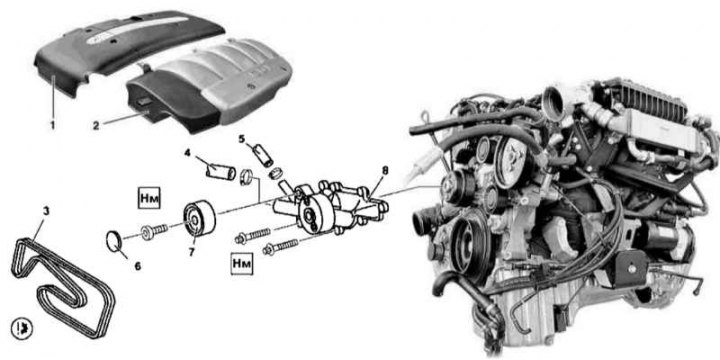
Water pump installation details on diesel models with M612 engine
1, 2 - Cylinder head cover trim panels; 3 - Auxiliary drive belt; 4, 5 - Cooling tract hoses; 6 - Plug; 7 - Guide roller; 8 - Water pump
1. Open the hood.
2. Remove the crankcase guard.
3. Drain the cooling system (see Chapter Routine care and maintenance).
4. Remove the trim panels (1 and 2).
5. Remove the fan assembly (see Section Removal and installation the cooling system fan assembly).
6. Install the air conditioning radiator/condenser protection screen (a metal or plastic plate measuring 400x680x1 mm equipped with a suitable support bracket).
7. Remove the accessory drive belt (3).
8. Disconnect the cooling system hoses (4 and 5) from the pump assembly (8) - if necessary, prepare replacement mounting clamps.
9. Pry off the plug (6) of the guide roller (7).
10. Remove the guide roller (7), under which one of the pump assembly mounting bolts is located.
11. Remove the mounting bolts and remove the water pump assembly (8).
12. Thoroughly clean the mating surfaces and prepare a new sealing gasket.
13. Installation is carried out in reverse order.
14. Finally, check the cooling system for signs of developing leaks.
M628
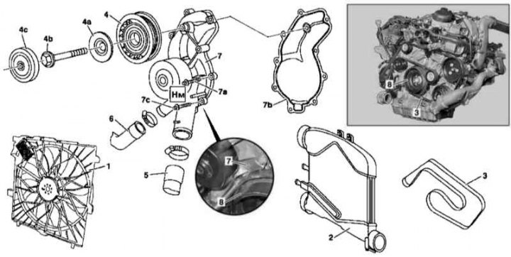
Water pump installation details for diesel models with M628 engine
1 - Fan assembly; 2 - Charge air cooler; 3 - Auxiliary drive belt; 4 - Guide roller; 4a - Washer; 4b - Bolt; 4c - Plug; 5, 6 - Cooling tract hoses; 7 - Water pump; 7a - Screw; 7b - Sealing gasket; 7c - Bolt; 8 - Torsional vibration damper/drive belt pulley
1. Jack up the car and place it on supports.
2. Remove the crankcase guard.
3. Drain the cooling system (see Chapter Routine care and maintenance).
4. Remove the air cleaner (see Chapter Fuel and exhaust systems).
5. Remove the fan assembly (1) (see Section Removal and installation the cooling system fan assembly).
6. Install the air conditioning radiator/condenser protection screen (a metal or plastic plate measuring 400x680x1 mm equipped with a suitable support bracket).
7. Remove the charge air cooler (see Chapter Fuel and exhaust systems).
8. Remove the accessory drive belt (3) (see Chapter Engine).
9. Remove the guide roller (4).
10. Disconnect the cooling system hoses (5 and 6) from the water pump (7) - if necessary, prepare replacement mounting clamps.
11. Remove the mounting screws and remove the pump assembly.
Note: To access the mounting bolt (7c) through the opening in the pulley (8), turn the crankshaft appropriately in the direction of normal rotation.
12. Installation is carried out in the reverse order - do not forget to replace the pump sealing gasket, the diagram of the location of the water pump fasteners on diesel models with the M628 engine is shown in the accompanying illustration.
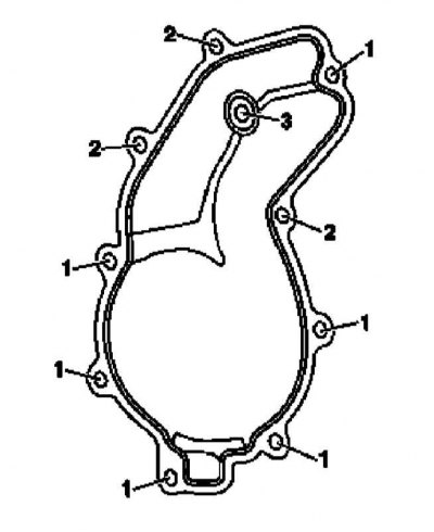
1 — M6x25
2 — M6x45
3 — M6x80 (tension roller bolt)
13. Finally, check the cooling system for signs of developing leaks.