
Models with 4-cylinder petrol engines
1. Disconnect the negative terminal of the modulator. Drain the liquid from the cooling system.
2. Remove the radiator fan and accessory drive belt pulley as described in paragraph 5.
3. Remove the thermostat as described in paragraph 4. then unscrew the bolts and remove the thermostat housing from the cylinder head. Loosen the hose clamps, separate the bypass hose from the pump and remove the thermostat housing from the engine (see fig. 7.3. a, b).
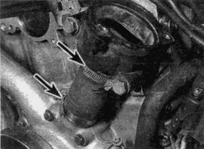
Pic. 7.3, a. Loosen hose clamps (shown by arrows)...
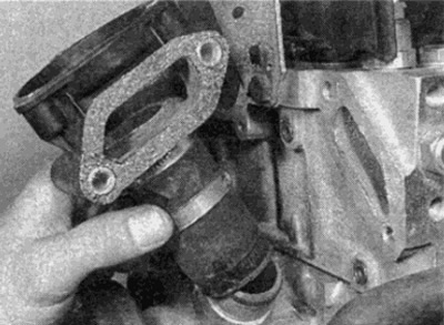
Pic. 7.3b....then separate the bypass hose from the pump and remove the thermostat housing from the engine
4. Loosen the clamps and disconnect the lower hose and the interior heater radiator return hose from the water pump (see fig. 7.4). Similarly, disconnect the additional hose on the left side of the pump.
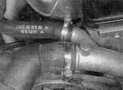
Pic. 7.4. Disconnect the lower radiator hose and heater return hose from the water pump
5. For early models with multiple drive belts, refer to paragraph 5 and remove the electromagnetic clutch from the water pump shaft.
6. On later models with a single ribbed belt, disconnect the plug on the electromagnetic clutch connector and release the cable from the holders - refer to paragraph 5.
7. Remove the alternator as described in Chapter 5 Part A. Turn away bolts and remove an arm of the generator from the water pump.
8. Loosen and remove the water pump mounting bolts, then lift the water pump up (see fig. 7.8, a, b). Make sure to mark the location of each bolt well, as they are of different lengths.
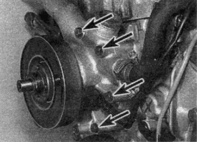
Pic. 7.8, a. Loosen and remove the water pump mounting bolts (the arrows show the bolts on the left side)...
Pic. 7.8b....then lift the water pump
Installation
9. Thoroughly clean the mating surfaces of the pump and cylinder block, removing all traces of the old gasket. Be careful not to scratch the surface as this will cause leaks. Similarly, clean the mating surfaces of the thermostat housing and cylinder head.
10. Installation of the water pump is carried out in the reverse order. Consider the following points (see fig. 7.10):
- A) Use a new gasket and tighten all boots to the correct torque (where specified in the technical data).
- b) Install the magnetic clutch as described in paragraph 5.
- V) Install and tension the accessory drive belt as described in Chapter 1.
- G) When finished, fill the cooling system as described in Chapter 1.
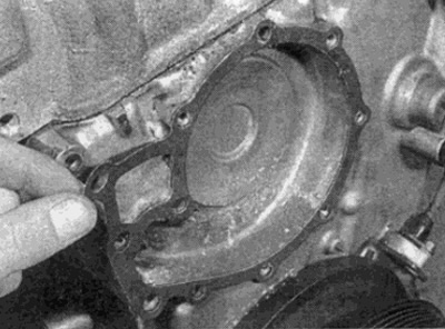
Pic. 7.10. Use a new gasket when installing
Models with 6-cylinder petrol engines
Removing
11. Disconnect the negative battery terminal. drain the cooling system as described in Chapter 1.
12. Remove the accessory drive belt and tensioner.
13. Referring to Chapter 10, remove the bolts and remove the power steering pump from the engine without disconnecting the hydraulic hoses (just take them out of the work area).
14. Remove the air cleaner and air intake trim (see chapter 4).
15. Access to the pump can be improved by removing the distributor (see Chapter 5 Part B) and drive belt cover panel.
16. Where it is provided on earlier models, turn away six bolts of fastening and shift the air conditioner compressor aside, without disconnecting hoses.
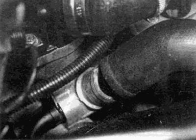
17. Loosen and remove the bolt, then disconnect the heater core return pipe from the water pump. Remove o-ring (see fig. 7.17, a, b). Release the tube from the holder on the radiator fan bracket.
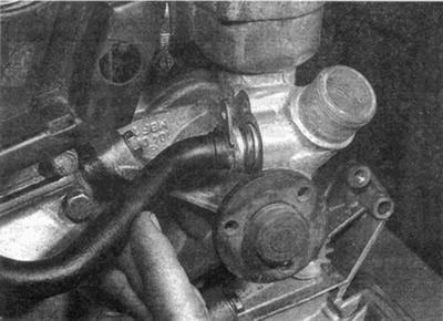
Pic. 7.17 a. Disconnect the heater core return pipe from the water pump...
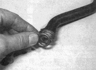
Pic. 7.17b....and remove the o-ring
18. On machines with an oil heat exchanger, remove the bolts and remove the coolant pipe union from the side of the pump. Remove the sealing ring. After unscrewing the screw, release the coolant pipe mounting bracket from the intake manifold support strut.
19. Refer to paragraph 4 and remove the thermostat.
20. Loosen the clamps and disconnect the cylinder head hoses and upper radiator hose from the water pump (see fig. 7.20, a, b).
Pic. 7.20 a. Disconnect the radiator...
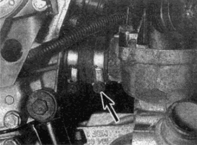
Pic. 7.20 b....and cylinder head hoses (shown by arrows) from the water pump
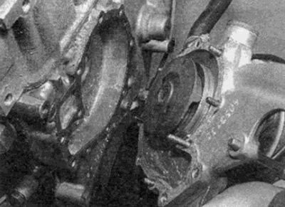
21. Loosen and remove the four mounting bolts, then lift the pump out of the engine (see fig. 7.21). Remove the two bushing sleeves and the o-ring.
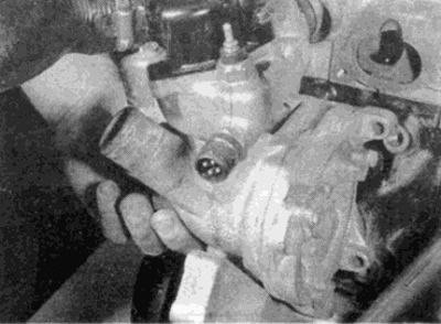
Pic. 7.21. Loosen and remove the bolts, then remove the water pump from the engine
Installation
22. Thoroughly clean the mating surfaces of the pump and cylinder block, removing all traces of the old gasket. Be careful not to scratch the surface as this will cause leaks.
23. Installation is carried out in the reverse order. Consider the following points:
- A) Access to most of the rear water pump mounting bolts is restricted. Insert them using a rod and a magnet or a magnetic hex wrench.
- b) Where required, tighten all bolts to the correct torque.
- V) Replace heater core return hose seal to pump, water pump seal to cylinder block, and thermostat seal to housing.
- G) Install and tension the accessory drive belt as described in Chapter 1.
- d) When finished, fill the cooling system as described in Chapter 1.
Models with diesel engines
Removing
24. Disconnect the negative battery terminal. Drain the cooling system as described in Chapter 1.
25. On models with electromagnetic fan engagement, refer to Chapter 1 and remove the accessory drive belt and tensioner.
26. Refer to paragraph 5 and remove the viscous or electromagnetic clutch of the radiator fan from the water pump (depending on what is installed).
27. On rayon mesh fan models, remove the drive belt as described in Chapter 1. After that turn out bolts and remove a pulley from the water pump.
28. Loosen the clamps and remove all hoses from the water pump housing (see fig. 7.28). Unscrew the return pipe of the heater radiator from the fittings and remove the sealing ring.
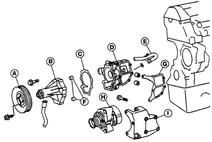
Pic. 7.28. Water pump (diesel engine models)
A Pulley
B Water pump
C Gasket
D Water pump housing
E Return tube
F Keys
G Gasket
H Alternator
I Generator support bracket
29. Remove the alternator as described in Chapter 5 Part A. Then unscrew the bolts and remove the alternator support bracket from the engine.
30. Turn away bolts of the case of the water pump and remove it from the block of the engine together with the pump. Remove the pad.
31. Turn away bolts and remove the pump from the case together with a laying.
Installation
32. Thoroughly clean the mating surfaces of the pump and cylinder block, removing all traces of the old gasket. Be careful not to scratch the surface as this will cause leaks.
33. Installation is carried out in the reverse order. Consider the following points:
- A) Use new gaskets and, where required, tighten all bolts to the correct torque.
- b) Install the radiator fan as described in paragraph 5.
- V) Install and tension the accessory drive belt as described in Chapter 1.
- G) When finished, fill the cooling system as described in Chapter 1.