



Contents: Removal ↡ Installation ↡
Removal
Petrol models with engines of the M119.97/98 series
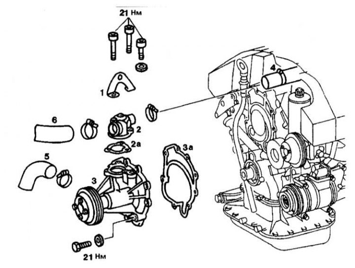
Water pump installation details on models with M119.97/98 series engines
1 - Eye; 2 - Lid; 3 - Cooling system pump; 2a, 3a - Gaskets; 4, 5, 6 - Branch pipes
1. Disconnect pipes (4), (5) and (6).
2. Unscrew the cover (2) with the eye (1). Replace the gasket (2a).
3. Loosen the pump mounting bolts (3).
4. Wipe the sealing surfaces. Replace the gasket (3a).
5. Remove the pump (3).
Petrol models with engines of the M120.97/98 series
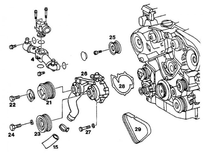
Water pump installation details for petrol models with M120.980/982 series engines
4, 15 - Cooling system pipes; 21 - Fan clutch; 22, 24, 27 - Bolts; 25 - Cooling system pump pulley; 26 - Cooling system pump; 28 - Gasket; 29 - Generator drive belt
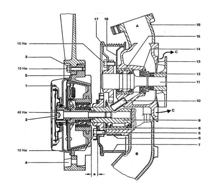
Design of water pump installed on 120 engines
1 - Casing; 2 - Mounting bolt; 3 - Bolt with washer; 4 - Impeller; 5 - Viscous coupling; 6 - Sealing ring; 7 - Clutch pulley; 8 - Flange; 9 - Bearing unit; 10 - Drainage tube; 11 - Pump shaft; 12 - Oil seal seal ring; 13 - Pump impeller; 14 - Seal; 15 - Bearing cage; 16 - Body; 17 - Pump drive pulley; 18 - liquid reflector disk; A - From the thermostat; B - From the radiator; C - To the engine crankcase; a - 7.85 mm
1. Loosen the fan clutch pulley (21) and coolant pump pulley (23) mounting bolts.
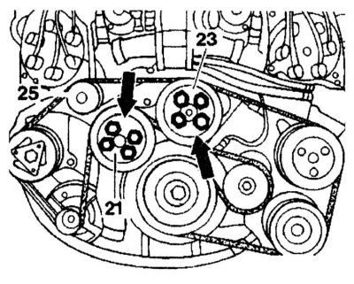
2. Remove the alternator drive belt. 3. Unscrew the fan clutch pulley (21) and the cooling system pump pulley (23).
4. Remove the guide roller (25) from the front right cover.
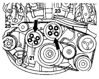
5. Disconnect the coolant hose from the coolant pump at the bottom.
6. Loosen the pump mounting bolts (26) and remove it.
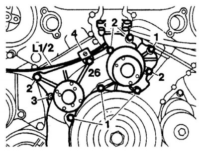
1 — Bolts M8x70
2 — Bolts M8x85
3 — Bolts M8x95
4 — Bolts M8x85 with a retainer for the TDC sensor wiring L1/2
Diesel models with engines of the OM603.971 series
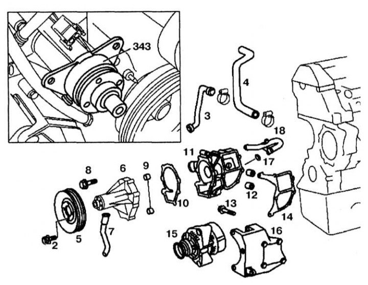
Water cooler installation details on diesel models with OM603.971 series engines
1. Drain the cooling system (see Chapter Routine maintenance).
2. Remove the radiator (see section Removal and installation of the cooling system radiator - installation details).
3. Remove the fan clutch.
4. Disconnect the negative cable from the battery.
5. Loosen the bolts (2) securing the pump sprocket.
6. Remove the generator drive belt.
7. Unscrew the pump pulley (5).
8. Disconnect pipes (3) and (4) from the pump.
9. Remove the generator (15).
10. Remove the generator support (16).
11. Remove the pump housing (11) together with the pump.
12. Replace the gasket (14). Wipe the sealing surfaces.
13. Unscrew the pump (6).
14. Replace the gasket (10).
Diesel models with engines of the OM606.961 series
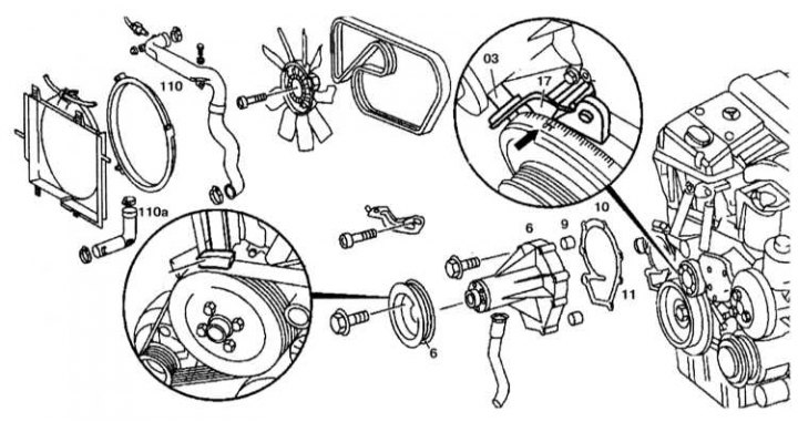
Water cooler installation details on diesel models with OM606.961 series engines
03 - Retainer; 5 - Cooling system pump pulley; 6 - Cooling system pump; 9 - Guide bushings; 10 - Gasket; 11 - Cooling system pump housing; 17 - TDC sensor; 110, 110a - Compressed air supply pipes
1. Drain the coolant.
2. Remove the fan clutch.
3. Loosen the coolant pump pulley (5) mounting bolt.
4. Remove the generator drive belt.
5. Remove the pulley (5) of the cooling system pump.
6. Set the piston of the first cylinder to the TDC position.
7. Unscrew the TDC sensor mounting bracket (17).
8. Check the TDC sensor installation and adjust it if necessary.
9. Unscrew the bolts securing the cooling system pump (6) to the pump body (11).
Installation
Petrol models with engines of the 119.97/98 series
Installation is carried out in the reverse order of removal.
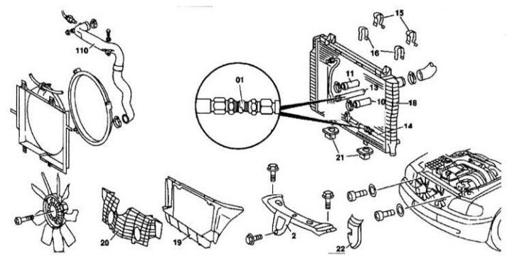
Tightening order of the cooling system pump mounting bolts on gasoline models with M119.97/98 series engines
Petrol models with engines of the M120.97/98 series
1. Wipe the sealing surfaces.
2. Replace the pump gasket.
3. Then install in the reverse order of removal. Check the cooling system for leaks.
Diesel models with engines of the OM603.971 series
Installation is carried out in the reverse order of removal.
Diesel models with engines of the OM606.961 series
Installation is carried out in the reverse order of removal. Replace the gasket (10) and wipe the sealing surfaces.
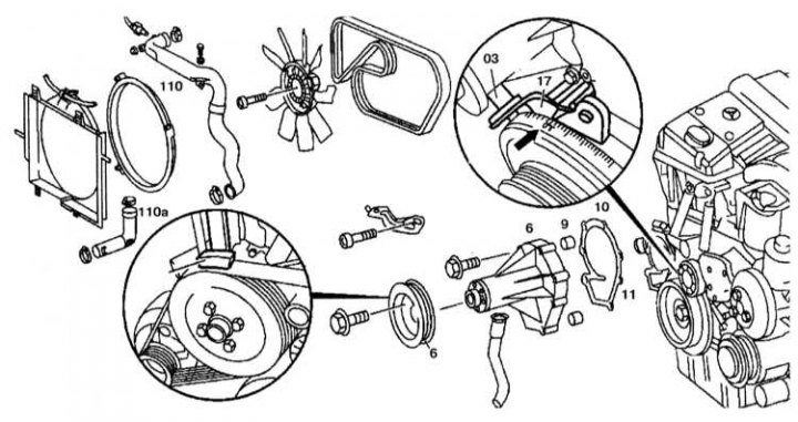
Water cooler installation details on diesel models with OM606.961 series engines
03 - Retainer; 5 - Cooling system pump pulley; 6 - Cooling system pump; 9 - Guide bushings; 10 - Gasket; 11 - Cooling system pump housing; 17 - TDC sensor; 110, 110a - Compressed air supply pipes