



Note: See also Section Comfort Chapters User manual
The air supplied by the ventilation system to the car's interior through the filter can be heated or cooled depending on the choice of the driver and passengers. The heater or air conditioner is located in the interior, in the housing under the instrument panel. The entire flow of air supplied to the interior is directed for heating or cooling through the same casing. The temperature and speed of the air flow are regulated using the controls located on the control panel.
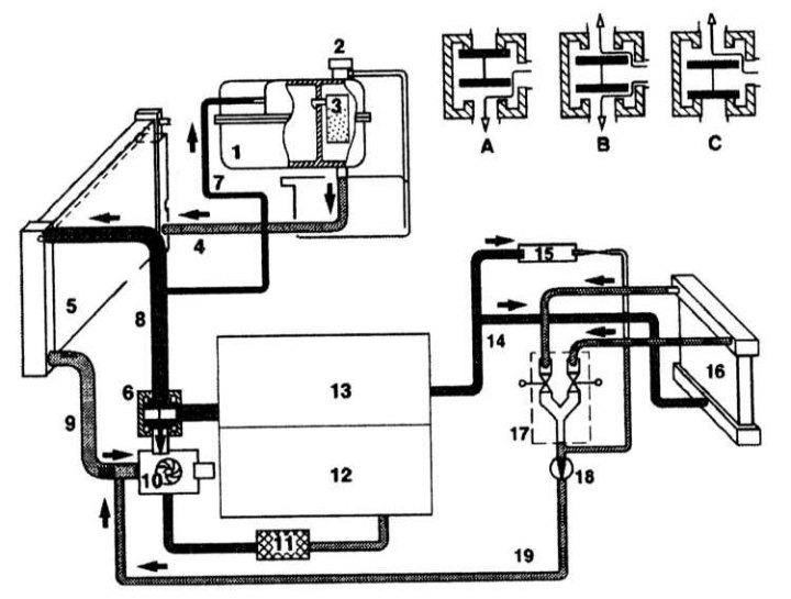
Cooling system diagram
1 - Expansion tank; 2 - Lid; 3 - Built-in silica gel tank; 4 - Intake pipe; 5 - Radiator; 6 - Thermostat; 7 - Ventilation tube; 8 - Flow from engine to radiator; 9 - Flow from radiator to engine; 10 - Cooling system pump; 11 - Oil radiator; 12 - Cylinder block; 13 - Cylinder head; 14 - Heater delivery pipe; 15 - Windscreen washer heater; 16 - Heater radiator; 17 - Double pulsation valve; 18 - Circulation pump; 19 - Heater return pipe
The heat generated by the engine is transferred by the coolant to the heater radiator located in the passenger compartment. The air flow supplied by the ventilation system passes through the radiator and is heated by the heat of the engine coolant flowing inside the radiator. The degree of heating is regulated by mixing cold and hot air in a certain ratio using a servo-driven mixing flap.
Used air is removed from the passenger compartment through ventilation openings with check valves.
The fresh air fan increases the air flow through the heat exchanger.
If it is necessary to turn off the fresh air supply, for example due to a bad smell, the system switches to recirculation mode, in which only the air that is present in the cabin circulates.
Switching the system to recirculation mode is confirmed by activation of the indicator lamp (see Chapter User manual).
Interior air conditioning system
Functional diagram of a typical air conditioning system
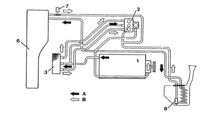
The working path of the front circuit of the K/V system
A — Coolant inlet port; B - Coolant return flow; 1 - Engine; 2 - Cabin heating pumping unit; 3 - Heat exchanger of the interior heater; 6 - Windshield heating radiator (wiper); 7 - Thermovalve, heated windshield (wiper); 8 - Thermovalve, windshield washer fluid heater
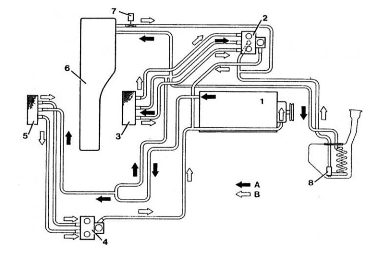
Working path of the rear circuit of the K/V system
A - Coolant inlet; B - Coolant return flow; 1 - Engine; 2 - Cabin heating pumping unit; 3 - Heat exchanger, heating system; 4 - Bleeding unit, rear climate control; 5 - Heater heat exchanger, rear climate control; 6 - Windshield heating radiator (wiper); 7 - Thermovalve, heated windshield (wiper); 8 - Thermovalve, windshield washer fluid heater
Work on the air conditioning system must be carried out by a specialized workshop. Never open the refrigerant circuit, as the refrigerant may cause frostbite if it comes into contact with the skin.
With the help of the air conditioning system, the air temperature in the cabin can be lowered below the outside temperature.
When the system is operating, the humidity in the cabin decreases. In damp weather, the incoming fresh air is pre-cooled, after which it is heated again to the set temperature. This is how it is dried. This procedure removes fogging of the windows.
The air conditioning system consists of a compressor, condenser, throttle, evaporator, refrigerant tank and pipelines. The refrigerant (type R134a) circulates in the system, which, depending on the temperature and pressure, can be in a liquid or gaseous state.
The air conditioner compressor is driven by the engine crankshaft via a ribbed belt. It creates a pressure of up to 30 bar in the cooling circuit of the unit, causing the refrigerant, which is a gas, to heat up. In the condenser, the refrigerant is cooled by the air flowing outside (cooling air remains in the external environment). As a result, the heated refrigerant condenses, turning into a liquid. Having high pressure, it passes through the throttle, as a result of which its pressure drops. After this, the refrigerant evaporates in the circuit, simultaneously cooling down strongly. In the evaporator, the refrigerant takes heat from the air blown through it. As a result, the air cools down. The cooled air enters the car interior. As a result of heating in the evaporator, the refrigerant turns into gas and under low pressure enters the compressor, after which the circulation process is repeated.
Safety precautions when servicing an air conditioner
The air conditioning system must be serviced only by trained technical personnel who are trained in safe operating practices using the proper equipment, observing depressurization rules, and are familiar with the methods of collecting and storing automotive refrigerant.
- Avoid contact of refrigerant with skin;
- Wear safety glasses when working near the air conditioning system;
- If refrigerant gets on your skin or eyes, do not rub the affected area. Rinse immediately with cold water for at least 15 minutes. Seek immediate medical attention or medical attention. Self-medication is not allowed;
- The refrigerant in a new cylinder is stored under pressure. Store the cylinder at a temperature not exceeding 50°C. Take measures to prevent the cylinder from falling from a height or other situations that may cause damage to it;
- Work should be carried out in a well-ventilated area. The refrigerant evaporates quickly, reducing oxygen supply and making breathing difficult;
- The gaseous refrigerant is heavier than air and should collect relatively quickly at a low level, such as under a car;
- When refrigerant burns, it produces toxic gas. Keep refrigerant away from open flames. Do not smoke. Avoid inhaling smoke when using a flame leak detector;
- When welding near an air conditioning system, exposure to high temperatures or open flames may occur. Overheating may cause pressure in the system to increase and ignite;
- Cleaning the condenser or evaporator with water vapor is not permitted. Only cold water or compressed air should be used.