



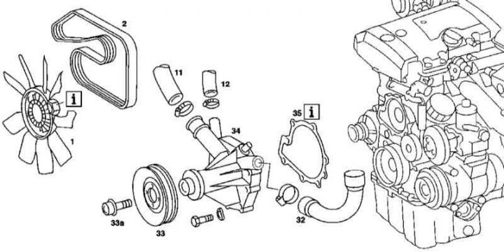
111 Series Engine Water Pump Installation Details
1. The installation details of the water pump for the 111 series engine are shown in the illustration to which all references in the text refer.
2. Remove the cooling fan assembly with viscous coupling (see Section Removal and installation the cooling system fan assembly).
3. Drain the cooling system (see Chapter Checking the cooling system and frost resistance of the coolant, replacing the liquid).
4. Disconnect the cooling system hoses (11, 12 and 13).
5. Loosen the combination bolts (33a) with washers securing the drive belt pulley (33).
6. Remove the accessory drive belt (2)
7. Remove the pulley (33).
8. Remove the mounting bolts and remove the water pump assembly (34) from the engine.
9. Carefully clean the mating surfaces and prepare a new sealing gasket (35).
10. Installation is carried out in reverse order.
11. Finally, check the cooling system for signs of developing leaks.
M112/113
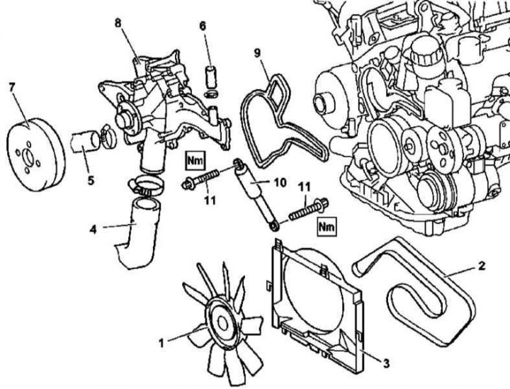
Water pump installation details for 112 and 113 series engines
1 - Assembly of the impeller with a viscous coupling; 10 - Vibration damper (not used on the models under consideration); 11 - Bolts
1. The installation details of the water pump for the 112 and 113 series engines are shown in the illustration, to which all references in the text refer.
2. Remove the engine trim panel/air cleaner.
3. Remove the fan assembly (see Section Removal and installation the cooling system fan assembly).
4. Disconnect the lower coolant hose from the radiator or water pump and drain the coolant from the radiator.
5. Remove the accessory drive belt (2).
6. Remove the accessory drive belt tensioner (see Chapter Engine).
7. Remove the cooling system hoses (4 and 5).
8. Disconnect the hose (6) from the liquid heat exchanger of the engine lubrication system.
9. Remove the water pump drive pulley (7).
10. Unscrew the mounting bolts and remove the pump assembly (8).
11. Installation is carried out in the reverse order - do not forget to replace the sealing gasket (9).
Diesel models
M612
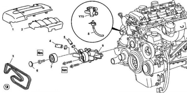
612 Series Engine Water Pump Installation Details
1. The installation details of the 612 series engine water pump are shown in the illustration to which all references in the text refer.
2. Drain the cooling system (see Chapter Checking the cooling system and frost resistance of the coolant, replacing the liquid).
3. Remove the trim panels (1 and 2).
4. Remove the fan assembly (see Section Removal and installation the cooling system fan assembly).
Material borrowed from an online resource [mercedesman]
5. Remove the accessory drive belt (3).
6. Remove the cooling system hoses (4 and 5).
7. Pry off the cover (6) of the guide roller (7).
8. Remove the guide roller (7).
9. Disconnect the fuel line (8) from the shut-off valve (Y75).
10. Remove the mounting bolts and remove the water pump assembly (9).
11. Thoroughly clean the mating surfaces and prepare a new sealing gasket.
12. Installation is carried out in reverse order.
13. Finally, check the cooling system for signs of developing leaks.
M628
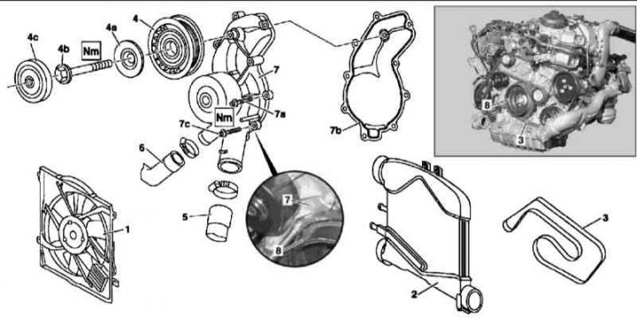
628 Series Engine Water Pump Installation Details
1 - Fan assembly; 2 - Charge air cooler (not installed on the models in question); 3 - Auxiliary drive belt; 4 - Guide roller; 4a - Washer; 4b - Bolt; 4c - Lid; 5, 6 - Cooling tract hoses; 7 - Water pump; 7a - Screw; 7b - Sealing gasket; 7c - Bolt; 8 - Torsional vibration damper/drive belt pulley
1. The installation details of the 628 series engine water pump are shown in the illustration to which all references in the text refer.
2. Drain the cooling system (see Chapter Checking the cooling system and frost resistance of the coolant, replacing the liquid).
3. Remove the fan assembly (1).
4. Remove the bypass hose of the air boost tract.
5. Remove the engine oil dipstick guide tube.
6. Remove the accessory drive belt.
7. Remove the guide roller (4).
8. Disconnect the cooling system hoses (5 and 6) from the water pump (7).
9. Remove the mounting screws and remove the pump assembly.
Note: To access the mounting bolt (7c) through the opening in the pulley, rotate the crankshaft in the normal direction of rotation accordingly.
10. Installation is carried out in reverse order - do not forget to replace the pump sealing gasket.
11. Finally, check the cooling system for signs of developing leaks.