
Note: This paragraph covers models equipped with standard automatic interior heating - does not cover models equipped with air conditioning; for more information contact paragraph 9.
Heater unit
Removing
1. Drain the cooling system as described in Chapter 1.
2. Remove the instrument panel as described in Chapter 11.
3. Loosen the cable clamp on the left side of the heater assembly and remove the screw on the connector.
4. Disconnect the connector from the back of the heater fan motor switch (see fig. 8.4).
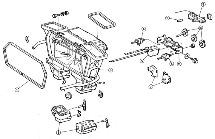
Pic. 8.4. Heater unit details
1 Seal
2 Air nozzle
3 Heater
4 Vacuum switch
5 Air distributor
6 Vacuum switch
7 Lids
8 Heater fan switch
9 Lamp
10 Switch buttons
11 Switch bracket
5. Disconnect vacuum lines and a wire from a lamp of illumination by the block of management of a heater.
6. Disconnect the heater radiator supply hose from the back of the cylinder head.
7. Place a container underneath the engine under the detachable hose.
8. Disconnect the heater core return hose from the thermostat housing. Using compressed air from a foot pump, squeeze any remaining coolant out of the heater core by inserting the pump hose into the heater core return hose port. The coolant will be forced out of the hole into the substituted container.
9. Turn away two bolts and separate a tube of a returnable hose from a heater radiator flange (see fig. 8.9).
Pic. 8.9. Loosen the return flow tube bolts (see fig. 8.9).
10. Pull off the right air tube on the heater block below the fluid return tube.
11. Remove the two bolts and separate the fluid supply pipe from the flange on the other side of the heater core.
12. Pull the left air duct on the heater block below the heater core inlet pipe.
13. Pull out from a partition of a motor compartment on the right side the holder of an inlet tube.
14. Loosen the support bracket nut below the inlet tube holder.
15. Turn away a nut of the right arm under a returnable tube.
16. Turn away from above the block of a heater two nuts of fastening.
17. Disconnect the control cable at the heater fan motor switch.
18. Disconnect the control cable from the main damper on the side of the heater block.
19. Remove the block of a heater from basic hairpins, lift it up and remove from the car.
Installation
20. Installation is carried out in the reverse order. When connecting the heater fan control cable, connect and secure the cable to the switch, then move the switch to the fan position "MAX". Connect the end of the control cable to the main choke lever, open the choke fully, then secure the cable sheath.
21. When finished, fill the cooling system as described in Chapter 1.
Heater radiator
Removing
22. Remove the heater block as described earlier in this paragraph.
23. Turn away screws on an inlet branch pipe of a heater.
24. Carefully unfasten all fasteners along the top surface on both sides and on the bottom surface of the heater block.
25. Disconnect the linkage from the left and right arms of the anti-fog device.
26. Push in the lock on the left damper of the anti-fogging channel, while pulling out the linkage connector lever.
27. Remove the gaskets from the left and right connections of the anti-fog nozzle.
28. Push out the air mixing damper link arms on the left and right arms
29. Remove the ball heads of the connecting levers of the left and right air mixing dampers from the spherical recesses.
30. Separate the two halves of the heater block and remove the air mixing dampers.
31. Turn away screws of fastening of a frame of a radiator of a heater. Remove the frame and remove the heater core.
Installation
32. Installation is carried out in the reverse order.
Heater fan motor
Removing
33. Remove the intake manifold cover from the top of the air box as described in Chapter 12.
34. Disconnect the vacuum hose at the heater valve (see fig. 8.34).
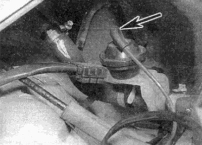
Pic. 8.34. Disconnect the vacuum hose (shown by arrow)
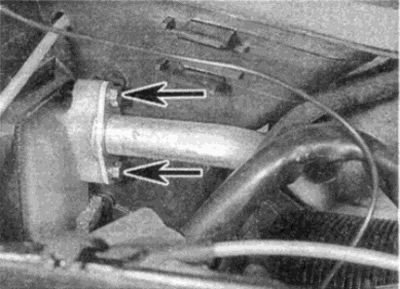
35. Turn off two screws on a cover of the electric fan of a heater (see fig. 8.35).
Pic. 8.35. Loosen the heater fan cover screws (shown by arrows)
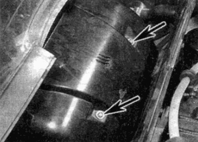
36. Lift the rubber sealing strip from the inner wall of the partition of the engine compartment and unscrew the two screws securing the partition on each side (see fig. 8.36).
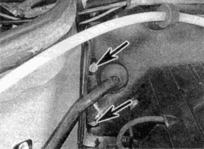
Pic. 8.36. Screws of fastening of an internal partition of a motor compartment (shown by arrows)
37. Move the septum wall up and forward. then remove the heater fan cover.
38. Loosen the cable ties and disconnect the motor plug.
39. Turn away bolts of fastening of the electrofan of a heater and remove the electric motor aside from the case (see fig. 8.39).
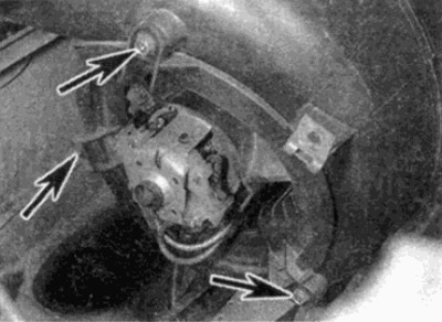
Pic. 8.39. Bolts of fastening of the electric motor of a heater
Installation
40. Installation is carried out in the reverse order. heater valve
Heater valve
Removing
41. Remove the intake manifold cover from the top of the air box as described in Chapter 12.
42. Slowly unscrew the cap of the expansion tank to reduce the pressure in the cooling system
43. Disconnect the vacuum hose from the heater valve located next to the heater electric fan in the air intake box.
44. Disconnect the cooling hoses and remove the valve from the bracket.
Installation
45. Installation is carried out in the reverse order. However, please note that the side of the valve, marked "water inlet" ("water inlet") should face towards the engine. When finished, add coolant.