
Cars BMW Cars Volkswagen Cars Chevrolet Cars Land Rover Cars Lada Cars Honda Cars Peugeot
English Русский
Български
Беларускі
Український
Српски
Hrvatski
Română
Polski
Slovenský
Magyar
Bookmark News and articles Sitemap Feedback Site search
MercedesMan.ru


A-Class C-Class E-Class G-Class M-Class S-Class Others
190 (W201) (1982-1993) W202 (1993-2000) W203 (2000-2007)
  • Main
  • C-Class
  • W201 (1982-1993)
  • Body
  • Interior (internal elements)
  • Instrument panel — removal and installation

Instrument panel — removal and installation (Mercedes-Benz C-Class W201)

0
Contents: Removal ↡ Installation ↡

Removal


1. Remove the instrument cluster as described in Chapter 12.

2. Remove the glove box as described in paragraph 41.

3. Remove the trim under the instrument panel on both sides. On the driver's side, the trim is secured with four screws and a clip, and on the passenger side, with three screws. Pry off the plugs to access the screws (see fig. 42.3).
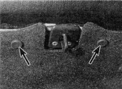
Fig. 42.3. Pry off the plugs (shown by arrows) and unscrew the screws

Fig. 42.3. Pry off the plugs (shown by arrows) and unscrew the screws


4. Pull the door seal from both sides of the A-pillar (see fig. 42.4).
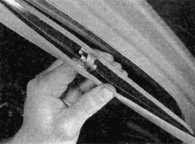
Fig. 42.4. Remove the door seal

Fig. 42.4. Remove the door seal


5. Remove both front pillar trim panels using a plastic wedge, pressing in the area of the retainer (see fig. 42.5).
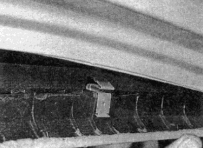
Fig. 42.5 Remove the front panel trims

Fig. 42.5 Remove the front panel trims


6. Loosen the mounting screw and remove the speaker grille from the top on both sides of the instrument panel.


7. Remove the top bolt on each side near the speakers (see fig. 42.7).
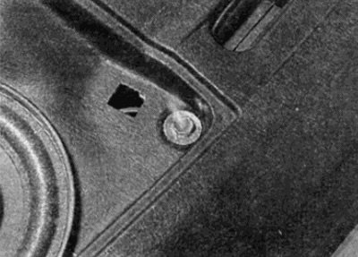
Fig. 42.7. Unscrew the top bolt next to the speaker

Fig. 42.7. Unscrew the top bolt next to the speaker


8. Using pliers and a protective cloth, pull the handle off the light switch, then unscrew the switch mounting nut (see fig. 42.8). Disconnect the wires and remove the switch.
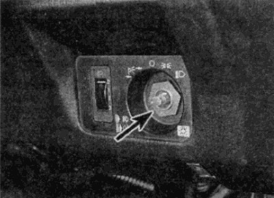
Fig. 42.8. Unscrew the light switch mounting nut (shown by arrow)

Fig. 42.8. Unscrew the light switch mounting nut (shown by arrow)


9. Pry up the headlight adjustment switch, disconnect the wires and vacuum hoses and remove the switch. Note that the hose tubes are purple on top and purple/yellow on the bottom at the base.

10. Pry up or push out the upper instrument panel switches from the back, mark the electrical connectors and disconnect the plugs. Remove the switches.


11. Unscrew the two mounting bolts, left and right, securing the instrument panel to the body reinforcement element (see fig. 42.11).
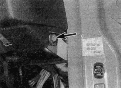
Fig. 42.11. Unscrew the instrument panel mounting bolts on the side (shown by arrow)

Fig. 42.11. Unscrew the instrument panel mounting bolts on the side (shown by arrow)


12. Remove the air ducts from the left and right air flow ducts (see fig. 42.12).
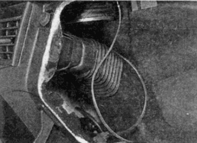
Fig. 42.12. Remove the air ducts from the air ducts

Fig. 42.12. Remove the air ducts from the air ducts


13. Mark the location, then disconnect the wires from the glove box light (see fig. 42.13).
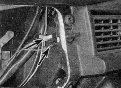
Fig. 42.13. Disconnect the glove box light wires

Fig. 42.13. Disconnect the glove box light wires


14. Unscrew the bolt securing the lower part of the instrument panel to the body reinforcement element (see fig. 42.14).
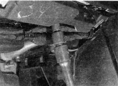


Fig. 42.14. Unscrew the lower bolt securing the instrument panel to the body reinforcement element

Fig. 42.14. Unscrew the lower bolt securing the instrument panel to the body reinforcement element


15. Loosen the instrument panel mounting screw on both sides of the remote control (see fig. 42.15).
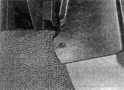
Fig. 42.15. Unscrew the side mounting screws

Fig. 42.15. Unscrew the side mounting screws


16. Using pliers and a protective cloth, remove the three heater control buttons.

17. Remove the heater fan switch button (see fig. 42.17).
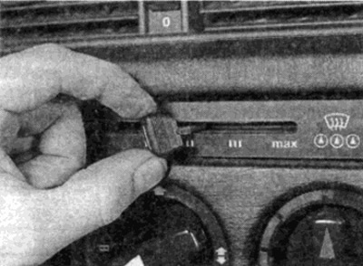
Fig. 42.17. Remove the heater fan switch button

Fig. 42.17. Remove the heater fan switch button


18. Unscrew the three nuts securing the heater control unit (see fig. 42.18).
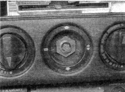


Fig. 42.18. Unscrew the nuts securing the heater control unit

Fig. 42.18. Unscrew the nuts securing the heater control unit


19. Using pliers and a protective cloth, remove the central air vents (see fig. 42.19).
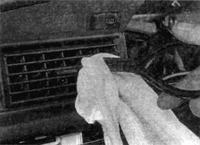
Fig. 42.19. Remove the central air vents

Fig. 42.19. Remove the central air vents


20. Remove the screws on each side of the central air vent holes (see fig. 42.20).
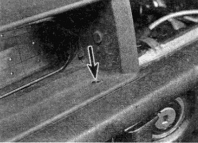
Fig. 42.20. Unscrew the screws in the center of the ventilation hole (shown by arrow)

Fig. 42.20. Unscrew the screws in the center of the ventilation hole (shown by arrow)


21. Carefully pry up the ignition switch trim (see fig. 42.21).
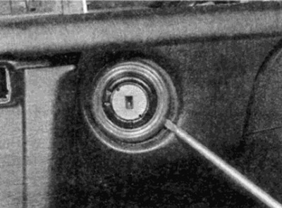


Fig. 42.21. Pry off the ignition switch trim

Fig. 42.21. Pry off the ignition switch trim


22. Close the fresh air flap lever and unscrew the bolt, acting through the slot in the lever (see fig. 42.22).
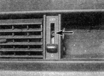
Fig. 42.22. Unscrew the bolt (shown by arrow) through the slot for the lever

Fig. 42.22. Unscrew the bolt (shown by arrow) through the slot for the lever


23. Pull the air hose off the back of the central air vents (see fig. 42.23).
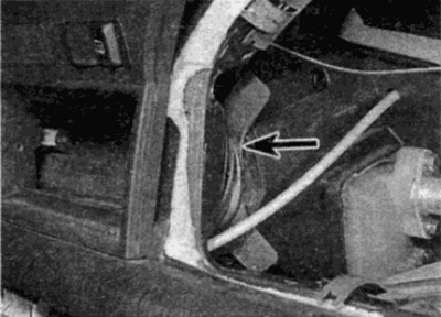
Fig. 42.24. Unscrew the bolt behind the glove box cover (shown by arrow)

Fig. 42.24. Unscrew the bolt behind the glove box cover (shown by arrow)


24. Loosen the mounting bolt behind the glove box cover (see fig. 42.24) and the inner nut on the base on the right side.
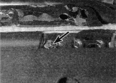


Fig. 42.23. Remove the air hose (shown by arrow) central ventilation channel

Fig. 42.23. Remove the air hose (shown by arrow) central ventilation channel


25. Remove the anti-fog air vents from the heater unit and remove the instrument panel from the passenger compartment.

Installation


26. Installation is carried out in reverse order.
This article is available at: russian, bulgarian, belarusian, ukrainian, serbian, croatian, romanian, polish, slovak, hungarian
The article has been verified: Lukyanov Nikita Ilyich
Share with friends:
◀ Previous
C-Class 190 (W201) / Interior (internal elements)
Next ▶

Glove Box — Removal and Installation
Central control panel — removal and installation
Seat belts — removal and installation
Rear seat — removal and installation
Front seats — removal and installation
 
More similar articles for repairing other models

☛ Lower Instrument Panel Cover Passenger Side — Removal and Installation Mercedes W168 (1997-2004)
☛ Removal and installation the instrument panel Mercedes W123 (1976-1985)
☛ Instrument panel and center console — general information Mercedes W463 (1999-2019)
☛ Instrument panel and center console Mercedes W163 (1997-2005)
☛ Instrument panel — general information Mercedes W140 (1991-1998)
☛ Instrument panel Mercedes Vito 1 (1996-2003)
Link in different formats to this article
Comments and feedback from visitors
No comments yet


How much will 29 + 49 ?


W203 (2000-2007) 
  • General information
  • Introduction to guide
  • User manual
  • Maintenance
  • Power unit
  • Gasoline engines
  • Diesel engines
  • Cooling system
  • Ventilation and heating
  • Supply system
  • Injection system (gasoline)
  • Injection system (diesel)
  • Exhaust system
  • Ignition and control system
  • Charge and launch systems
  • Transmission
  • Mechanical gearbox
  • Automatic gearbox
  • Clutch and drive shafts
  • Differential
  • Chassis
  • Brake system
  • Car suspension
  • Steering
  • Body
  • Exterior (external elements)
  • Interior (internal elements)
  • Electrical equipment
  • Equipment and devices
  • Lighting system
  • Electrical diagrams (2000)
  • Electrical diagrams (since 2001)
W202 (1993-2000) 
  • General information
  • User manual
  • Driving a car
  • Car care
  • Maintenance
  • Power unit
  • Gasoline engines
  • Diesel engines
  • Lubrication system
  • Cooling system
  • Heating and ventilation
  • Ignition system
  • Fuel system
  • Injection system (gasoline)
  • Injection system (diesel)
  • Exhaust system
  • Transmission
  • Clutch
  • Car gearbox
  • Chassis
  • Suspension, wheels and tires
  • Steering
  • Brake system
  • Body
  • Exterior (external elements)
  • Interior (internal elements)
  • Doors and windows
  • Electrical equipment
  • Equipment and devices
  • Power devices
  • Lighting system
  • Electrical circuits
190 (W201) (1982-1993) 
  • General information
  • Introduction to the guide
  • Operation and care
  • Maintenance (gasoline)
  • Maintenance (diesel)
  • Troubleshooting
  • Power unit
  • Petrol engine I4
  • Petrol engine V6
  • Diesel engines
  • Engine overhaul
  • Cooling and heating
  • Power system (carburetor)
  • Injection system (gasoline)
  • Injection system (diesel)
  • Exhaust system
  • Charge and start system
  • Ignition system (I4)
  • Ignition system (V6)
  • Diesel heating system
  • Transmission
  • Clutch
  • Mechanical gearbox
  • Automatic gearbox
  • Cardan shaft and axle shafts
  • Chassis
  • Brake system
  • Car suspension
  • Steering
  • Body
  • Exterior (external elements)
  • Interior (internal elements)
  • Doors, locks and windows
  • Electrical equipment
  • Equipment and devices
  • Electrical circuits
 
MercedesMan.ru © 2017–2026 · Mobile version · Read about Mercedes · Sitemap: EN BG BY UA RS HR RO PL SK HU · Feedback · Site search · Bookmark A-Class (W168) · C-Class (W201) · C-Class (W202) · C-Class (W203) · E-Class (W123) · E-Class (W124) · E-Class (W210) · G-Class (W463) · M-Class (W163) · S-Class (W116, petrol) · S-Class (W126, petrol) · S-Class (W140) · S-Class (W220) · Sprinter · Vito 1 · Vito 2 · Vario 814D ·
 
We only use cookies without which some of the site's features may not be available.