
Removing
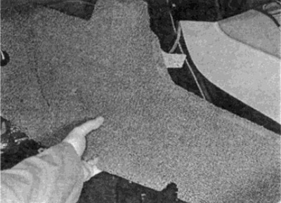
1. On manual transmission models, release the shift lever boot on the console cover and slide the boot up the shift lever (see fig. 40.1, a). Holding the back of the plastic middle part of the console cover with your fingers, lift the cover, then slide it back and lift it off (see fig. 40.1, b, c). Please note that the lid is secured with two very tight rear latches and two tabs at the front (see fig. 40.1, g).
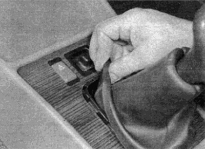
Pic. 40.1. A. Release the gear selector boot...
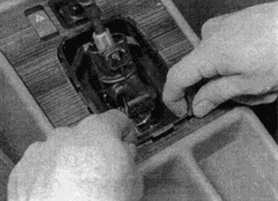
Pic. 40.1b....lift the back cover of the console...
Pic. 40.1, c....then slide it back and remove
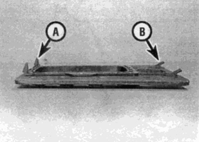
Pic. 40.1. d. Rear retainers (A) and front paws (IN) console covers
2. On automatic transmission models, pry up the console cover at the rear using a plastic wedge inserted into the gap between the gear selection plate and the cover. Slide the lid back to separate the two front tabs and lift up.
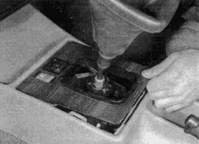
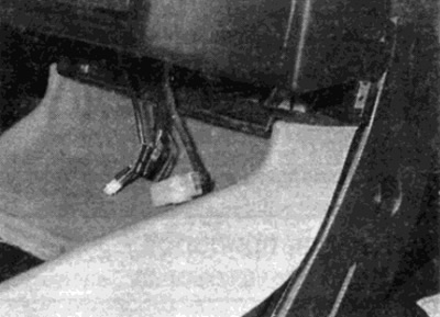
3. Disconnect the wire plugs from the console switches, after marking their location, and remove the cover (see fig. 40.3).
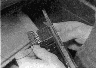
Pic. 40.3. Disconnect the wires on the console cover switches
4. Refer to Chapter 9 and loosen the parking brake adjuster under the vehicle so that the brake control lever can be set nearly vertical.
5. Remove the front ashtray, then unscrew the two upper screws securing the ashtray body to the instrument panel (see fig. 40.5).
Pic. 40.5. Loosen the screws securing the front ashtray housing
6. Pull out the ashtray body, disconnect the wires and the backlight and remove the body (see fig. 40.6, a, b).
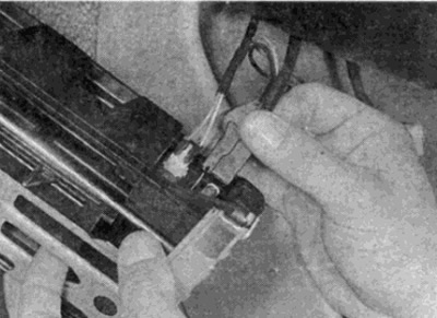
Pic. 40.6 a. Disconnect wires...
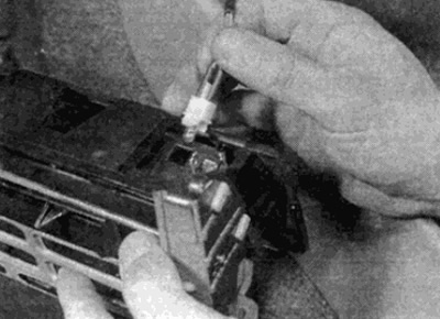
Pic. 40.6, b... and holder for the backlight on the ashtray body
7. Remove the floor mats on both sides in the footwells.
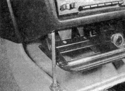
8. Remove the mounting screws that secure the instrument panel to the edges of the console on each side (see fig. 40.8).
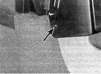
Pic. 40.8. Loosen the screw on the side (shown by arrow)
9. Loosen the retainer and fixing screw (where it is installed) and remove the foot pad on the driver's side (see fig. 40.9).
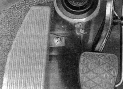
Pic. 40.9. Loosen the foot pad lock
10. Remove the front floor mats on both sides.
11. On the passenger side, unscrew the lower mounting screw and remove the front panel trim (see fig. 40.11, a, b).
Pic. 40.11, a. Loosen the screw securing the panel cladding...
Pic. 40.11, b - and remove the lining
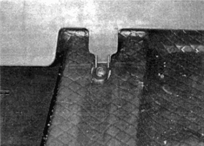
12. Remove the central fixing screw and remove the mat on both sides of the console (see fig. 40.12). On the driver's side, the mat is additionally fastened with a retainer.
Pic. 40.12. Remove the mat from both sides of the remote
13. Pull the handle on the parking brake lever and remove it forward along the lever (see fig. 40.13, a, b).
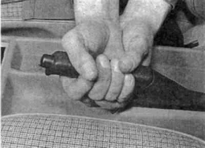
Pic. 40.13. A. Pull the lever handle...
Pic. 40.13, b....and take it off the lever
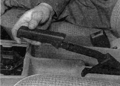
14. Pull the brake lever up and remove the lower lever trim (see fig. 40.14).
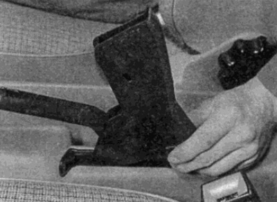
Pic. 40.14. Remove the parking brake lever lower cover
15. Turn away a bolt of fastening of the panel in front of the lever of a choice of transfers or the case of a choice of transfers (see fig. 40.15).
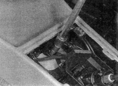
Pic. 40.15. Loosen the front bolt
16. Remove the rear ashtray, then remove the ashtray holder by prying the lower retainer from below (see fig. 40.16, a, b).
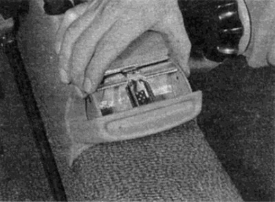
Pic. 40.16. A. Remove rear ashtray...
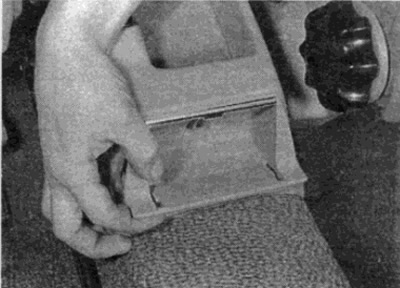
Pic. 40.16 b....and body
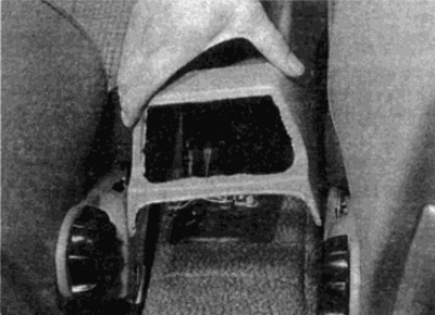
17. Working through the hole for the ashtray, unscrew the rear bolt of the remote control.
18. Move both front seats back and tighten the parking brake lever up as far as it will go.
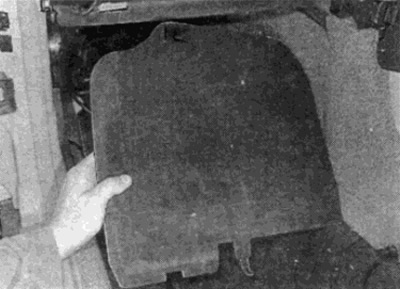
19. Lift the remote back and disconnect it from the instrument panel in front (see fig. 40.19, a, b).
Pic. 40.19, e. Raise the console from behind...
Pic. 40.19. b....and detach it from the front
20. Raise the console above the parking brake lever and remove it from the passenger compartment.
Installation
21. Installation is carried out in the reverse order. When finished, adjust the parking brake as described in Chapter 9.