
Fan with thermoviscous gearing
Removing
Note: On petrol models, this operation requires the use of a special tool to secure the radiator fan pulley to the fan support bracket. If you do not have such a device and cannot borrow it from your dealer, you can make a replacement from a piece of rod with a diameter of 4 mm. For diesel models, in order to avoid damage to the fan pulley and related parts, it is recommended to purchase a branded fixing tool.
1. Disconnect the negative battery terminal. Remove the accessory drive belt (see chapter 1).
2. Remove the screws and separate the plastic panels at the top and bottom of the heatsink. Where provided, remove the coolant hose from the retainer on the top panel.
3. On models with a fixed fan shroud, unhook the metal clips and separate the shroud from the heatsink. Pass the shroud over the top of the fan and position it between the motor and the fan blades - refer to paragraph 3.
4. On split shroud models, remove the locking pin and rotate the shroud ring to the left to disengage it from the shroud. Pass the shroud ring over the top of the fan and position it between the motor and the fan blades - refer to paragraph 3.
5. Release the metal spring clips, then separate the fan shroud from the radiator and remove it from the engine compartment, then remove the shroud ring.
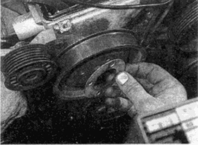
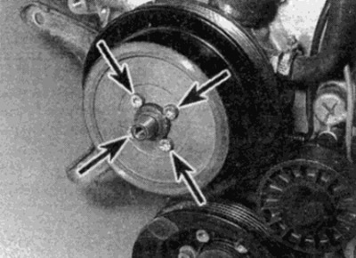
6. On petrol models, rotate the fan pulley so that the fixing hole on the rear face lines up with the notch on the fan support bracket. Insert locking tool (see point 1) so that the pulley is locked on the support bracket and cannot turn (see fig. 5.6).
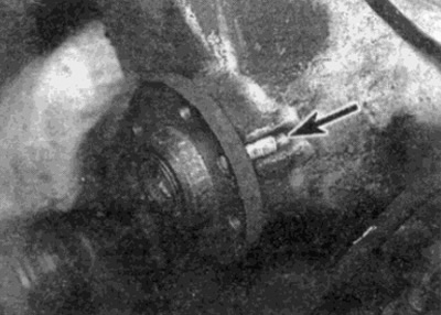
Pic. 5.6. Radiator fan pulley shaft fixed with a homemade tool (shown by arrow) - for clarity, the fan, clutch and pulley are removed
7. On diesel models, the fan pulley shaft must be locked with a proprietary tool that grips the edges of the fan pulley without removing the drive belt. Since the center bolt of the viscose clutch is tightened with a large torque, it is not recommended to use a homemade tool.
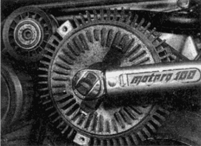
8. Loosen and remove the bolts, then separate the fan blade assembly from the engagement clutch. On models with a non-separable casing, remove the casing from the engine compartment (see fig. 5.8).
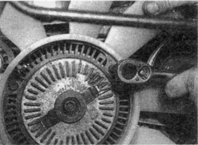
Pic. 5.8. Loosen and remove the bolts and separate the fan blades from the viscous coupling
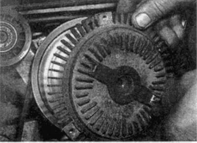
9. Loosen and remove the center bolt, then separate the engagement assembly from the pulley shaft. If necessary, turn out bolts and remove a pulley from a shaft see fig. 5.9. a-d).
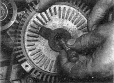
Pic. 5.9, a. Loosen and remove the center bolt...
Pic. 5.9. b....then separate the clutch from the pulley shaft
Pic. 5.9, c. If necessary, unscrew the bolts, remove the washer...
Pic. 5.9, d.... and remove the pulley from the shaft
Installation
10. Installation is carried out in the reverse order. Check that all bolts are tightened to the correct torque (see fig. 5.10).
Pic. 5.10. Make sure the coupling center bolt is tightened to the correct torque
Fan with electromagnetic gear
Removing
11. Disconnect the negative battery terminal. On 4-cylinder petrol models, do the following:
- A) Drain the liquid from the cooling system (see chapter 1).
- b) Remove the radiator (see paragraph 3).
- V) Remove the air cleaner (see chapter 4).
12. Refer to Chapter 1 and remove the accessory drive belt from the water pump pulley.
13. Remove the central mounting bolt and remove the fan from the pump spindle (see fig. 5.13).
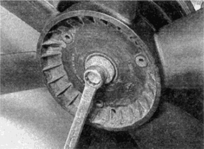
Pic. 5.13. Remove the central mounting bolt and remove the fan from the pump spindle
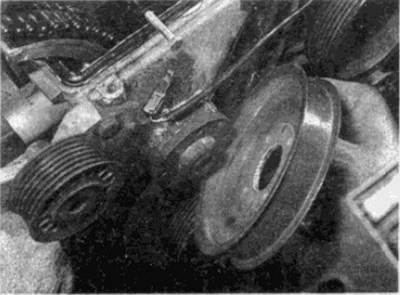
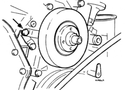
14. Loosen and unscrew the bolts, then remove the water pump pulley from the spindle (see fig. 5.14).
Pic. 5.14. Loosen and unscrew the bolts (shown by arrows), then remove the pump pulley from the shaft
15. On early models with multiple accessory drive belts, remove the three bolts securing the clutch housing to the water pump and pump bracket. Remove the clutch, disconnect the plug on the connector and remove the assembly from the vehicle (see fig. 5.15, a, b).
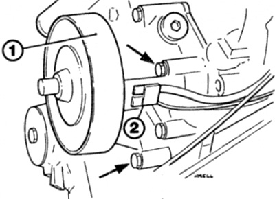
Pic. 5.15. A. Arrangement of the left bolts of fastening of the coupling (shown by arrows) - early models
1 Clutch housing
2 Connector plug
Pic. 5.15. b. Clutch bracket bolt location (shown by arrow) - early models
16. On later models with a single drive belt, remove the bolts on the back of the clutch housing that secure it to the base plate. Remove the gear, disconnect the plug from the connector and remove the assembly from the engine.
Installation
17. Installation is carried out in the reverse order. Install the washers on the fan mounting bolt as shown in fig. 5.17 and tighten all fasteners to the correct torque.
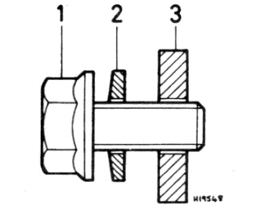
Pic. 5.17. Fan mounting bolt, washer and spacer
1 Bolt
2 Cup washer
3 spacer