
Petrol models
Assembling the impeller with a viscous clutch
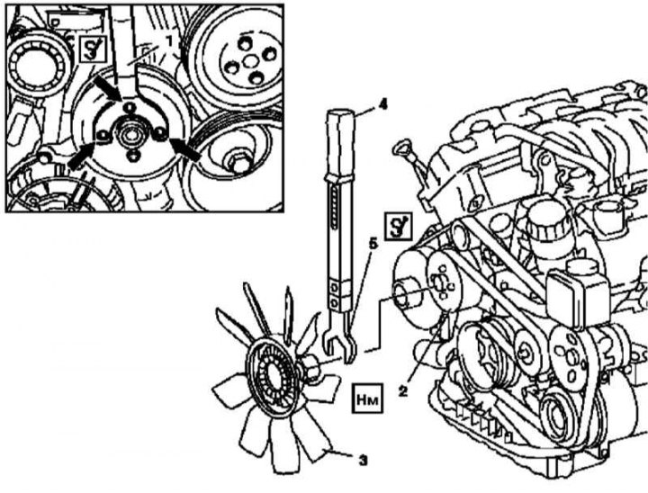
Installation details of the fan impeller with viscous clutch on gasoline models
1 - Holder; 2 - Drive belt pulley; 3 - Assembly of the impeller with a viscous coupling; 4 - Torque wrench; 5 - Horn nozzle
Fan shroud
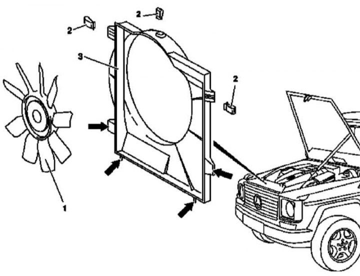
Installation details of the fan assembly casing on gasoline models and diesel models with the M612 engine
1 - Assembling the impeller with a viscous coupling
2 - Clips
3 - Fan assembly casing
Diesel models
M612
Assembling the impeller with a viscous clutch
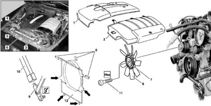
Installation details of the fan impeller with a viscous clutch on diesel models with an M612 engine
1, 2 - Cylinder head cover trim panels; 3 - Overflow lines of the cooling path; 4 - Air intake; 5 - Upper transverse bulkhead; 6 - Spring clips; 7 - Viscous fan clutch; 8 - Impeller; 9 - Screwdriver; 10 - Torque wrench; 11 - Central screw; 12 - Fan assembly casing
1. Remove panels (1 and 2) cylinder head cover finishes.
2. Jack up the car and put it on stands.
3. Remove the crankcase protection.
4. Empty the cooling system (see chapter Ongoing care and maintenance).
5. Remove overflow lines (3).
6. Remove the air intake hose (4) air cleaner mounted on the mudguard of the wing.
7. Remove the decorative grille (see chapter Body).
8. Remove the upper transverse bulkhead (5) and take it aside assembled with the hood lock.
9. Release the spring clips (6) fastening of the casing of the fan assembly.
10. Place the holder on the bolts of the fan drive pulley, - make sure the holder fits correctly (see illustration Viscous Clutch Fan Impeller Installation Details on Gasoline Models).
11. Using a screwdriver (9) and torque wrench (10) loosen the right-hand thread center bolt (11), then remove the fan assembly (complete with casing) from the engine compartment.
12. Loosen the impeller (8) from the clutch (7).
13. Installation is carried out in the reverse order. Impeller (8) must be labeled «FRONT» forward in the direction of travel, - there is a guide ledge on the landing ring. Also make sure that the fastening tabs (arrows) casing hit the support nodes of the assembly and from below on the radiator.
14. Finally, check the cooling system for signs of leak development.
Fan shroud
Details of installation of a casing of the fan on diesel models with the 612 engine are shown in the illustration Details of installation of a casing of a fan assembly on petrol models and diesel models with the M612 engine.
M628
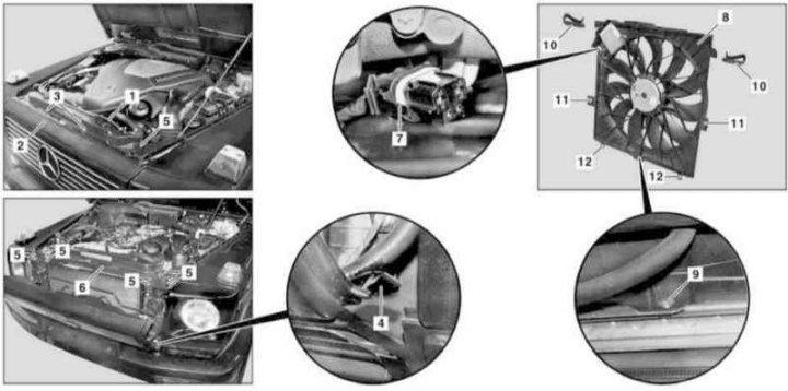
Installation details of the fan assembly on diesel models with the M628 engine
1 - Ventilation line; 2 - Decorative grille; 3 - Mounting bolts; 4, 11, 12 - Fasteners; 5 - Bolts; 6 - Upper transverse beam of the front end; 7 - Wiring connector; 8 - Casing fan assembly; 9 - Bolt; 10 - Clips
1. Remove the air cleaner (see chapter Power supply and exhaust systems).
2. Separate from the radiator and lay aside the ventilation line (1), prepare a replacement bandage.
3. Remove the decorative grille (2) (see chapter Body).
4. Turn out bolts (5) and remove the upper cross member (6), - do not forget to release the hood latch release drive cable from the latches.
5. Disconnect the wiring connector (7) on the casing (8) fan assembly.
6. Jack up the car and put it on stands.
7. Remove the crankcase protection.
8. Turn out a fixing bolt (9), release the latches (1) and release the cover (8) fan assembly from the guides on the radiator and the support brackets of the latter.
9. Installation is carried out in the reverse order.
10. Finally, check the cooling system for signs of leaks.