
Cover check
Checking the cooling system cover
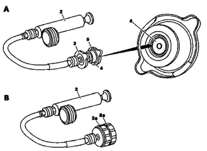
A - bayonet type cover; 2 - Tester; 3 - Nozzle cover; 4 - Nozzle; 5 - Cover of the cooling system; 6 - Pressure reducing valve; B - Threaded type cover; 2 - Tester; 3a - Nozzle; 5a - Cooling system cover
Two-step type screw cap design
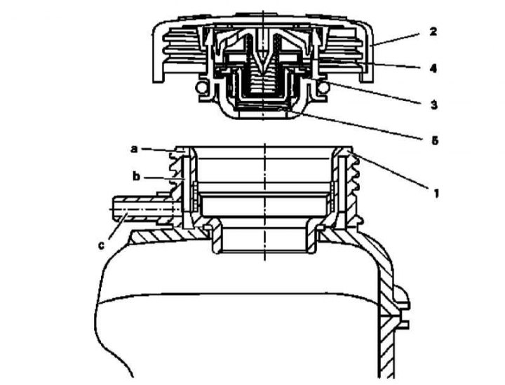
1 - The neck of the expansion tank; 2 - Cover of the cooling system; 3 - Lower pressure reducing valve; 4 - Upper pressure reducing valve; 5 - Vacuum valve; a - Ventilation drilling; b - Ring undercut; c - Outlet nipple
1. After the engine has cooled down, carefully open the cover of the cooling system - the cover may have a bayonet (A) or threaded (IN) design: the first is used on gasoline models, the second on diesel models. It makes sense to dwell a little more on the principle of operation of the threaded cover used on models equipped with the 612 series engine. The cover opens in two steps: when the pressure in the system rises to the first control value, the lower pressure reducing valve built into the cover opens, providing access to the internal chamber of the cover. With a further increase in pressure, the upper pressure reducing valve is activated and the pressure is released through special ventilation holes in the neck of the expansion tank - the excess of the gas phase enters the annular groove of the neck and then through the outlet nipple into the atmosphere. This design avoids overfilling the expansion tank.
Bayonet cap
1. Connect the nozzle (4) with lid (3) to the tester (2).
2. Connect to the nozzle (4) cooling system cover (5).
3. Having created the required pressure (see Specifications), make sure that the pressure reducing valve operates correctly (6), - the valve must be pressed tightly against the rubber seal (arrow) and rise slightly when the spring is released.
4. Replace the defective cover.
Screw cap two stage type
1. Connect to tester (2) nozzle (3a).
2. Screw the cooling system cap onto the nozzle (5a).
3. Having pumped up the required pressure (see Specifications), check that both pressure reducing valves operate properly.
4. Replace the defective cover.
Hose replacement
Note. See also Sections Checking the condition and replacing the engine compartment hoses, localizing leaks and Checking the functioning of the cooling system and frost resistance of the coolant, changing the fluid.
1. Identified during the inspection of the condition of the components of the cooling system (see chapter Ongoing care and maintenance) damaged hoses must be replaced without fail.
2. Drain the liquid from the cooling system (see chapter Ongoing care and maintenance).
3. Loosen and move aside the mounting collars. Carefully remove the hose from the inlets. If the hose cannot be removed, try to rotate it, being careful not to damage the nozzle, the failure of which is fraught with significant costs - remember that the radiator pipes are among the rather fragile components! If the hose does not give in, it must be cut - the cost of a new hose is not comparable to the cost of purchasing a replacement radiator. Before cutting the hose, prepare a replacement element of the correct size.
4. When installing a new hose, first put the clamps on it, then install the hose on the nozzles. If tie-type clamps were originally installed, replace them with screw / worm. To facilitate the installation of rigid hoses, moisten the inner surfaces of their ends with soapy water or heat them in hot water - to avoid delamination, do not lower the hose into boiling water.
5. After installing the hose on the branch pipes, check the correctness of its laying in the engine compartment. Install the clamps on the ends of the hose, passing them behind the flare pipes, and tighten them.
6. Fill the cooling system (see chapter Ongoing care and maintenance).
7. Start the engine and check for signs of coolant leaks from the serviced unit.