
Note. The following are the settings used when performing the procedures in this chapter. Detailed regulatory information can be obtained from authorized Mercedes-Benz workshops. Separate characteristics are also given in the text of the Chapter and, if they are mandatory, are highlighted in bold.
Note. The values listed below are only typical for all engines of the considered series.
Petrol models
Common parameters
| engine's type | |
| V-twin, 6-cylinder, DOHC, water-cooled, timing chain and microprocessor controlled |
| V-twin, 8-cylinder, DOHC, water-cooled, timing chain and microprocessor control |
| Application range | |
| 112.945 |
| 113.962 |
| 113.982 |
| Engine volume, l | |
| M112 | 3.2 |
| M113 | |
| 5.0 |
| 5.5 |
| Number of valves per cylinder | 3 |
| Compression ratio | 10.0:1 |
| Compression pressure, atm | |
| 12 ÷ 14 |
| 9.0 |
| 1.5 |
| The order of operation of the cylinders | |
| 1-5-3-6-2-4 |
| 1-5-4-8-6-3-7-2 |
| valve clearances | Automatic adjustment, - hydraulic lifters |
Cylinder head
Classification of cylinder head gaskets for engines
Designation | Volume | Cylinder diameter | Marking | |
112.945 | 3.2 | 92.00 | A 1120160320/0420 |
|
113.962 | 5.0 | 97.00 | A 1130100220/0320 | |
113.982 | 5.5 | No information | No information | No information |
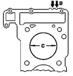
Dimensions of cylinder head bolts
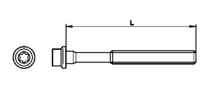
| Thread | M11 |
| Length (L), mm | |
| 141.5 |
| 144.5 |
Valve guides
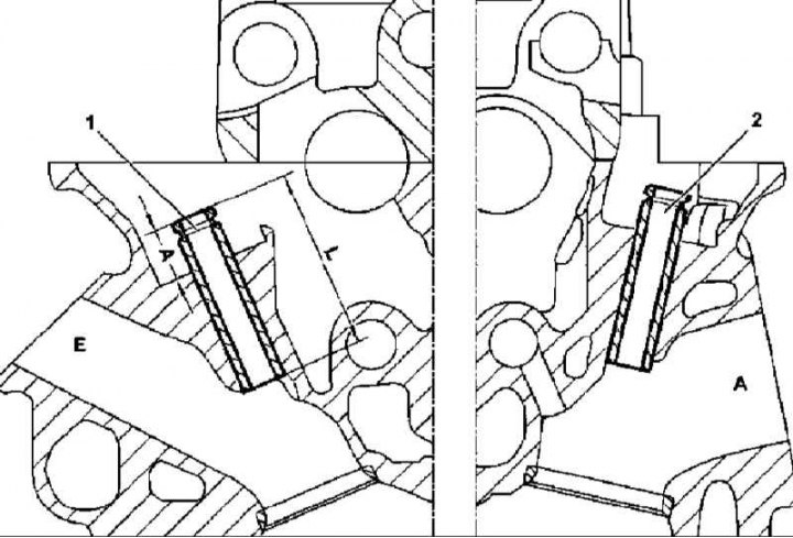
Valve guide seating pattern
1 - Intake valve guide
2 - Exhaust valve guide
A - Mounting depth of the sleeve
L - Full sleeve length
| Diameter of the seat for the valve guide bushing, mm | |
| 12.500 ÷ 12.511 |
| 12.520 ÷ 12.531 |
| 12.700 ÷ 12.711 |
| 13.100 ÷ 13.111 |
| Valve guide outer diameter, mm | |
| 12.540 ÷ 12.551 |
| 12.560 ÷ 12.571 |
| 12.740 ÷ 12.751 |
| 13.140 ÷ 13.151 |
| Valve guide length, mm | |
| 50 |
Geometric characteristics of the guide sleeve, mm | A 14.3±0.2 |
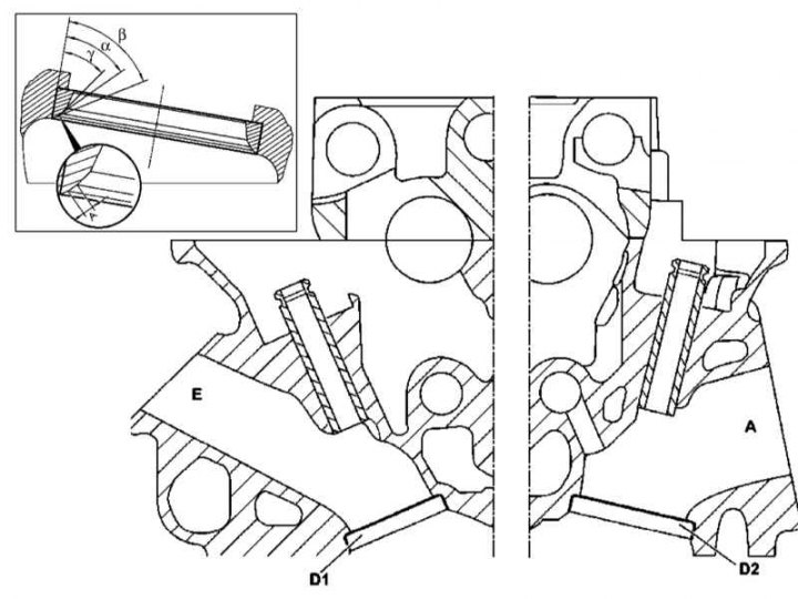
Installation details and geometrical parameters of valve seats (112 and 113 series engines)
D1 - Inlet valve seat socket
D2 - Exhaust valve seat socket
a — Bevel working angle
b - Upper correction angle
g — Lower correction angle
A - Width of the working chamfer of the saddle
Valve seats
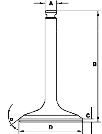
112 and 113 series engines
A - rod diameter
B - Length
C - plate height
D - Plate diameter
a — Chamfer angle
| Geometric parameters of valves (see resist. illustration) | |
| D, mm | |
| M112 | |
| 36 ± 0.1 |
| 41 ± 0.1 |
| M113 | |
| 38 ± 0.1 |
| 43 ± 0.1 |
| WITH (for new valve), mm | |
| 1.2 |
| 1.6 |
| A, mm | |
| 6.975 |
| 6.970 |
| V, mm | |
| M112 | |
| 119.40 ± 0.2 |
| 122.25 ± 0.2 |
| M113 | |
| 119.10 ± 0.2 |
| 121.80 ± 0.2 |
Cylinder block
Carter
| Cylinder diameter, mm | |
| M112 | |
| Standard size | |
| 89.900 ÷ 89.915 |
| 89.950 ÷ 89.965 |
| Repair size | 90.150 ÷ 90.165 |
| M113 | |
| Standard size | |
| 97.000 ÷ 97.015 |
| 97.050 ÷ 97.065 |
| Repair size | 97.250 ÷ 97.265 |
Crankshaft
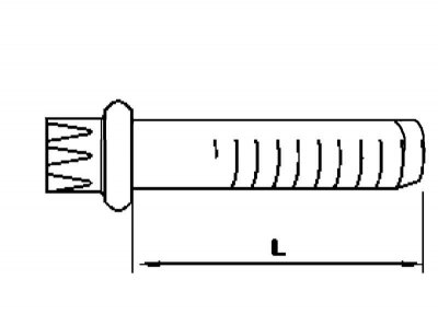
| Dimensions of connecting rod bearing cap bolts (see resist. illustration) | |
| Thread | M8x1 |
| Length, mm | |
| 47 |
| 47.6 |
Designations of persistent half rings of a cranked shaft
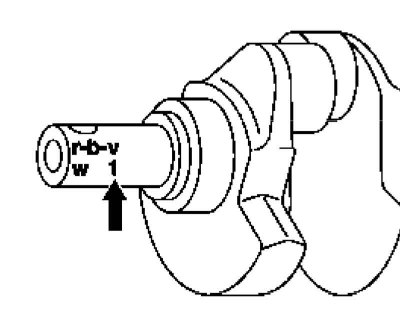
Block cylinders | crankshaft pin | Thrust half rings | Axial shaft play, mm | ||
Symbol | Inscription | Symbol | Marks- rovka | ||
Code | N | O | N | Alphanumeric code | 0,10 ÷ 0,266 |
Code | N1 | 1 | N1 | Alphanumeric code | 0,10 ÷ 0,266 |
balance shaft (series 112)
Maximum allowable length of the counterweight mounting bolt, mm | 50.7 |
Connecting rod and piston assemblies
| Piston diameter, mm | |
| M112 | |
| Standard size | |
| 89.872 ÷ 89.902 |
| 89.872 ÷ 89.902 |
| Repair size | 90.122 ÷ 90.152 |
| M113 | |
| Standard size | |
| 96.972 ÷ 97.000 |
| 97.022 ÷ 97.050 |
| Repair size | 97.222 ÷ 97.250 |
| The maximum allowable piston backlash, mm | 0.043 |
| The value of the radial play of the connecting rod bearings (new bearings), mm | 0.026 ÷ 0.054 |
Axial play of connecting rods
Insert color coding | Axial connecting rod size, mm | |
Upper liners (connecting rods) | Bottom liners (lids) | |
Yellow | Yellow | 0,026 ÷ 0,054 |
Blue | Red | 0,026 ÷ 0,054 |
Red | Blue | 0,026 ÷ 0,054 |
| Piston ring dimensions, mm | |
| Compression rings | |
| M112 | 83.2x1.5x3.1 |
| M113 | |
| 97.0x1.2x3.5 |
| 97.0x1.5x3.1 |
| Oil scraper ring | |
| M112 | 83.2x3.5x3.5 |
| M113 | |
| 97.0x1.5x4.0 |
| 97.0x3.5x3.5 |
Tightening force of threaded connections, Nm
| Engine oil pan drain plug (M14) | 30/32 |
| Oil filter housing cover | 25 |
| Self-tapping bolt for fastening the tensioner to the timing cover | |
| 35 |
| 25 |
| Bolts of fastening of a damper of a tensioner of a belt | |
| accessory drives | |
| 25 |
| 35 |
| Tensioner mounting bolts | 25 |
| Fitting unit for connecting the supply gas line to the fuel line | 38 |
| Flange connection of the exhaust pipe of the exhaust system with the exhaust manifold | 20 |
| Bolts of fastening of a starter to a crankcase of the engine | 42 |
| Bolts of fastening of pillows of forward support to a subframe | 35 |
| M8 bolts fastening the torque converter to the drive disk | 42 |
| Bolts of fastening АТ to the engine | |
| 40 |
| - |
| Attachments for hydraulic lines to steering pump | |
| pressure line | |
| - |
| 45 |
| return line | 2 |
| Screws of fastening of the K/V compressor to a basic arm | 20 |
| Bolts of fastening of a cover of a drive GRMk to the block and a head of cylinders | 20 |
| Bolt M8x78 fastening the guide pulley of the A/C drive belt and auxiliary units to the timing drive cover | 68 |
| Water pump mounting bolts | |
| |
| |
| 14 |
| 10 |
| |
| 35 |
| 25 |
| 10 |
| Fastening of a pulley of a drive of the water pump | 10 |
| Bolts of fastening of a casing of the thermostat (M6) | 10 |
| Steering pump mounting bolts | |
| |
| 35 |
| 20 |
| 25 |
| Bolts of fastening of the inlet pipeline to heads of cylinders (M8) | 20 |
| Chain tensioner in the timing cover | 80 |
| Bolt of fastening of sprockets of camshafts (М12x45) | |
| 50 |
| Pull up to 90° |
| Hall sensor camshaft in the cylinder head | 8 |
| Bolts of fastening of bridges of bearings of camshafts to headskhilindrov | |
| |
| 15 |
| - |
| |
| 10 |
| Pull up to 90° |
| Bolts of fastening of sprockets of camshafts (M12x45) | |
| 50 |
| Pull up to 90° |
| Bolts of fastening of a head of cylinders | |
| |
| 10 |
| 30 |
| Pull up to 90° |
| Pull up to 90° |
| 20 |
| Bolts of fastening of covers of heads of cylinders | 10 |
| Nut of fastening of a connecting tube to the EGR valve | 40 |
| Flange connection of the exhaust pipe of the exhaust system with the exhaust manifold | 20 |
| Nuts of fastening of a final collector | 16 |
| Engine End Cover Bolts | 10 |
| Vibration damper center bolt | |
| 200 |
| Pull up to 95° |
| Bolts of fastening of a driving disk to a cranked shaft | |
| 45 |
| Pull up to 90° |
| Bolts of fastening of covers of radical bearings | |
| |
| |
| 20 |
| Pull up to 90° |
| 30 |
| |
| 30 |
| Pull up to 90° |
| Bolts of fastening of covers of the lower heads of connecting rods | |
| 5 |
| 25 |
| Pull up to 90° |
| Bolt M7x16.5 fastening the locking plate to the balancing shaft (M112) | 15 |
| Bolt of fastening of a counterweight to a balancing shaft (M112) | |
| 20 |
| Pull up to 90° |
| Bolts/nuts of fastening of a pillow of a back support of a suspension bracket of the power unit | |
| 35 |
| 35 |
| Nuts of fastening of a cross beam to a car frame | 35 |
| Bolts for fastening the left and right side supports of the suspension of the power unit to the engine crankcase | |
| 20 |
| Pull up to 90° |
| Bolts of fastening of pillows of forward support of a suspension bracket of the power unit | |
| 35 |
| 65 |
| Oil filter housing cover | 25 |
| Bolts of fastening of a casing of assembly of the oil filter | 70 |
| Fastening of the liquid heat exchanger of the oil filter | 11 |
| Oil pan drain plug (M14) | 30 |
| Self-tapping bolts securing the lower section of the oil pan to the upper | |
| 14 |
| 10 |
| Bolts of fastening of the top section of the pallet crankcase to the block of cylinders | |
| 9 |
| 20 |
| Oil level sensor mounting bolts | |
| to the upper section of the oil pan | 10 |
| Bolts of fastening of oil atomizers | 15 |
| Oil pump mounting bolts (M8x30) | 20 |
Diesel models
Note. The values listed below are only typical for all engines of the considered series.
Common parameters
| engine's type | |
| inline (R), 5-cylinder, DOHC, turbocharged, water-cooled, timing chain |
| V-shaped, 8-cylinder, DOHC, turbocharged, water-cooled, timing chain |
| Application range | |
| 612.965 |
| 628.962 |
| Engine volume, l | |
| 2.7 |
| 4.0 |
| Number of valves per cylinder | 4 |
| Compression pressure, atm | |
| 29 ÷ 35 |
| 18 |
| Maximum allowable difference in readings between cylinders | 3.0 |
| The order of operation of the cylinders | |
| 1-2-4-5-3 |
| 1-5-4-8-6-3-7-2 |
| valve clearances | Not regulated, because applied hydraulic compensators |
Cylinder head
M612
Dimensions of cylinder head bolts
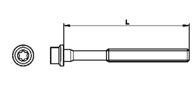
| Thread | M12 |
| Length, mm | |
| |
| 102 |
| 104 |
| |
| 107 |
| - |
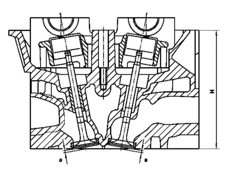
Details of installation of valves in a head of cylinders (612 series engines)
a - Fitting a new valve with a new seat
H - Cylinder head height
| Total height of the cylinder head, mm | |
| Rated value | 126.85 ÷ 127.15 |
| Limit value | - |
Valve seats
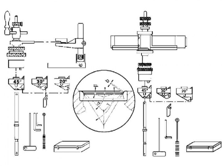
Valve seat boring (612 series engines)
b - Bevel width
a - The angle of inclination of the working chamfer
g — Correction angle
| Valve seat geometry | |
| All valves | |
| 45° (-30') |
| 1.0 ÷ 1.5 |
| 30° (± 15') |
| 0.9 ÷ 1.1 |
| Maximum allowable ovality, mm | 0.03 |
Valves
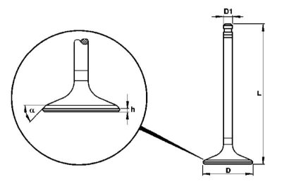
D - Plate diameter
h — Height of the cylindrical part of the dish (belt)
D1 - Rod diameter
L - Valve length
| Plate diameter (D), mm | |
| 30.1 ÷ 30.3 |
| 28.3 ÷ 28.5 |
| Height of the cylindrical part (girdle) dishes (h), mm | |
| 1.7 ÷ 1.9 |
| Angle of inclination of the working chamfer (a) | |
| 45° (+15') |
| Rod diameter (D1), mm | |
| 6.960 ÷ 6.975 |
| 6.955 ÷ 6.970 |
| Surface reinforcement of the saddle | |
| Absent |
| sodium filling | |
| Absent |
| Valve length (L), mm | |
| 104.7 ÷ 104.9 |
| 104.5 ÷ 104.9 |
| Plate identification marking | |
| E 611 01 |
| A 611 01 05 |
| Distance from the end of the valve stem to the base of the camshaft bearing (T), mm | |
| 17.1 ÷ 17.9 |
| Fitting a new valve with a new seat (A), mm | |
| 1.1 ÷ 1.5 |
| 1.0 ÷ 1.4 |
Series 628
Dimensions of cylinder head bolts
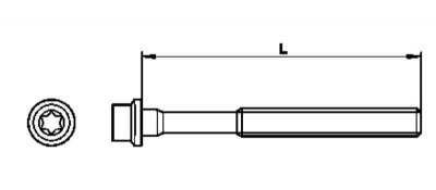
| Thread | M12 |
| Length, mm | |
| 201.5 |
| 203 |
Cylinder block
Series 612
Flywheel
| The limit value of the transverse runout of the ring gear, mm | 0.4 |
| Ring gear centering sleeve diameter, mm | 276.05 (± 0.05) |
Carter
| Diameter of beds of main bearings, mm | 62.500 ÷ 62.519 |
| Thrust bearing bed width, mm | 19.979 ÷ 20.000 |
| Maximum permissible value of ovality / taper of the beds of main bearings, mm | 0.02 |
Crankshaft
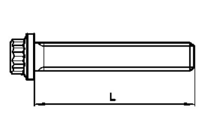
| Bolt sizes for main bearing caps | |
| Thread | M11 |
| Length (L), mm | |
| 61.8 ÷ 62.2 |
| 63.8 |
| Crankshaft play in main bearings, mm | |
| |
| 0.03 ÷ 0.05 |
| 0.08 |
| |
| 0.10 ÷ 0.25 |
| 0.3 |
Main bearing shells
| Thickness of main bearing shells (top and bottom liners), mm | |
| Standard size (Ø 58.00 mm) | |
| 2.255 ÷ 2.260 |
| 2.260 ÷ 2.265 |
| 2.265 ÷ 2.270 |
| 2.270 ÷ 2.275 |
| 2.275 ÷ 2.280 |
Connecting rod and piston assemblies
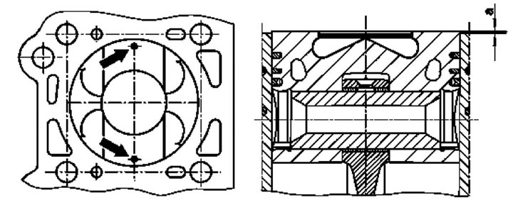
| Piston protrusion (A) in the new crankcase, mm | 0.38 ÷ 0.62 |
| The value of the side play of the piston rings, mm | |
| 0.12 ÷ 0.16 |
| 0.05 ÷ 0.09 |
| 0.03 ÷ 0.07 |
| The size of the gaps in the locks of the piston rings, mm | |
| 0.22 ÷ 0.42 |
| 0.20 ÷ 0.40 |
| 0.20 ÷ 0.40 |
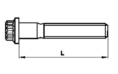
| Bolts of fastening of the lower heads of connecting rods | |
| 8x1 |
| |
| 47 ± 0.3 |
| 48 |
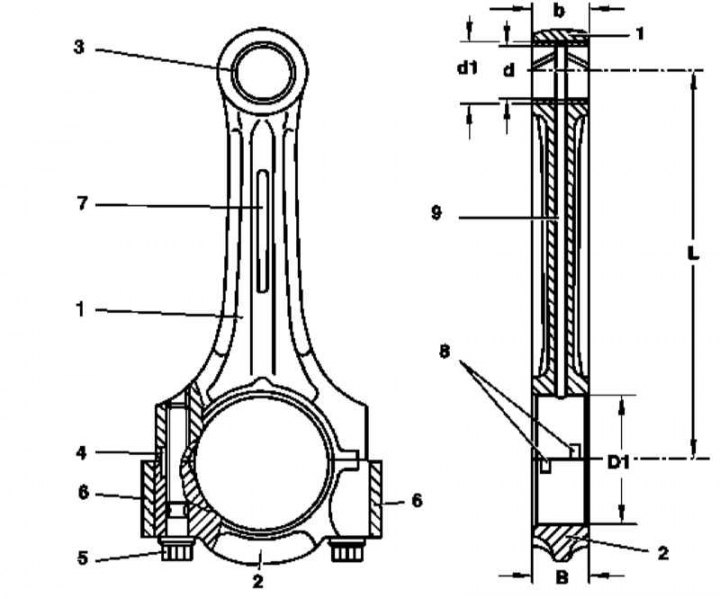
1 - Connecting rod; 2 - Lower head cover; 3 - Bushing; 4 - Guide sleeve; 5 - Bolt; 6 - Balancing weight; 7 - Marking area; 8 - Grooves for the tongues of the liners; 9 - Oil flow; 10 - Oil splash drills
| Connecting rod dimensions | |
| Distance between connecting rod bearing centers and piston pin bore (L), mm | 148.970 ÷ 149.030 |
| Connecting rod width (B and b), mm | 21.940 ÷ 22.000 |
| Connecting rod inner diameter (D1), mm | 51.600 ÷ 51.614 |
| Maximum allowable values of ovality and taper of the bed of the connecting rod bearing, mm | 0.02 |
| The maximum allowable amount of twisting of the connecting rod over a length of more than 100 mm | 0.100 |
| Maximum allowable value of misalignment of the connecting rod heads, mm | 0.045 |
| Connecting Rod Bushing Inner Diameter (d), mm | 30.018 ÷ 30.024 |
| Connecting Rod Bush Base Diameter (d1), mm | 32.500 ÷ 32.525 |
| The value of the backlash of the piston pin in the connecting rod, mm | 0.018 ÷ 0.024 |
| Maximum allowable weight difference of connecting rod assemblies, g | 2 |
Series 628
Carter
| Diameter of beds of main bearings, mm | |
| base value | 74.500 ÷ 74.519 |
| 74.500 ÷ 74.506 |
| 74.506 ÷ 74.512 |
| 74.512 ÷ 74.519 |
| Thrust bearing bed width, mm | 25.29 ÷ 25.50 |
| Maximum permissible value of ovality / taper of the beds of main bearings, mm | 0.02 |
Crankshaft
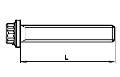
| Dimensions of bolts for fastening the lower section of the crankcase (main bearing cap bridge) | |
| Thread | M11 |
| Length (L), mm | |
| |
| 113 |
| 115 |
| |
| 135 |
| 137 |
| Crankshaft play in main bearings, mm | |
| |
| 0.03 ÷ 0.05 |
| 0.08 |
| |
| 0.10 ÷ 0.25 |
| 0.3 |
Main bearing shells
| Thickness of main bearing shells (top and bottom liners), mm | |
| Standard size (Ø 70.00 mm) | |
| 2.252 ÷ 2.257 |
| 2.257 ÷ 2.262 |
| 2.262 ÷ 2.267 |
| 2.267 ÷ 2.272 |
| 2.272 ÷ 2.277 |
Connecting rod and piston assemblies
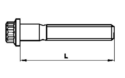
| Bolts of fastening of the lower heads of connecting rods | |
| Thread | 8x1 |
| Length (L) (see resist. illustration), mm | |
| 47 |
| 48 |
| The value of the side play of the piston rings, mm | |
| 0.12 ÷ 0.16 |
| 0.065 ÷ 0.110 |
| 0.03 ÷ 0.07 |
| The size of the gaps in the locks of the piston rings, mm | |
| 0.40 ÷ 0.55 |
| 0.25 ÷ 0.50 |
| 0.20 ÷ 0.40 |
Tightening force of threaded connections, Nm
| All engines | |
| Oil filter housing cover | 25 |
| Bolt of fastening of the fuel filter to the air distributor | |
| 14 |
| 9 |
| Screw of a coupling collar of fastening of the fuel filter (M612) | 9 |
| Series 612 | |
| Screws of fastening of the finishing panel of a cover of a head of cylinders | 10 |
| Screws of fastening of the finishing panel of the air distributor | 10 |
| Turbocharger air distribution arm support bracket bolts | 20 |
| Steering pump pressure line attachment points | |
| - |
| 45 |
| Hollow bolt of the union connection of the oil outlet line to the radiator | 30 |
| Bolts of fastening of the K/V compressor to a cover of the GRM drive | 20 |
| Bolts of fastening to the AT engine | |
| 40 |
| - |
| Bolts of fastening of a forward cover of a head of cylinders | 14 |
| Bolts of fastening of a head of cylinders to a cover of a drive of GRM (M8) | 20 |
| Bolts for fastening the timing cover to the engine crankcase | |
| - |
| 20 |
| Bolts of fastening of the pallet crankcase | |
| |
| 9 |
| 20 |
| - |
| 9 |
| 9 |
| Oil pan drain plug (M14) | 30 |
| Vibration damper center bolt | |
| |
| 200 |
| Pull up to 90° |
| |
| 325 |
| Pull up to 90° |
| Bolts of fastening of the K/V compressor to a cover of the GRM drive | 20 |
| Bolts of fastening of covers of bearings of camshafts to a head of cylinders | 9 |
| Bolt of fastening of an asterisk of a final camshaft | 18 |
| Bolt of fastening of an intermediate asterisk of TNVD | 40 |
| Timing chain tensioner to timing chain cover | 80 |
| Bolts of fastening of a head of cylinders | |
| 20 |
| |
| 60 |
| Pull up to 90° |
| Pull up to 90° |
| Pressure line nut injection pump/fuel distribution line | 20 |
| Knot for connecting the front catalytic converter to the turbocharger | 30 |
| Bolt of fastening of a line of removal of oil of a turbocharger | 9 |
| Bolts of fastening of a basic arm to a turbocharger | 30 |
| Bolts of a distributive sleeve of a path of pressurization of air | |
| - |
| 16 |
| Air path clamps | 3 |
| Bolt of fastening of a support arm to a distributive sleeve of a path of pressurization of air | 20 |
| Support Bracket to Engine Mounting Bracket Bolt | 40 |
| Bolts for fastening the electric motor for shutting off the intake port to the air distribution sleeve of the boost path | 9 |
| Nuts of fastening of a final collector on a head of cylinders | 30 |
| Bolts of fastening of a back face cover of the engine | 9 |
| Bolts of fastening of a flywheel/drive disk to a cranked shaft | |
| 45 |
| Pull up to 90° |
| Oil filter housing cover | 25 |
| Fastening of the liquid heat exchanger of the oil filter | 15 |
| Bolts of fastening of the pallet crankcase | |
| |
| 9 |
| 20 |
| - |
| 40 |
| 9 |
| Bolts of fastening of the sensor of level of oil to the pallet of a crankcase | 14 |
| Oil pump mounting bolts | 18 |
| Bolts of fastening of covers of the lower heads of connecting rods (connecting rod bearings) | |
| 5 |
| 25 |
| Pull up to 90° |
| Bolts of fastening of covers of radical bearings of a cranked shaft (M11) | |
| 55 |
| Pull up to 90° |
| Series 628 | |
| Auxiliary drive belt tensioner in the crankcase | 30 |
| Knot for connecting the front catalytic converter to the turbocharger | 15 |
| Bolts of fastening of the hydrotransformer to a driving disk (M8) | 42 |
| Union nuts/hollow bolts for fitting lines of the ATF cooling path | 35 |
| Steering pump pressure line attachment points | |
| - |
| 45 |
| Hollow bolt of the union connection of the oil outlet line to the radiator | 30 |
| Bolt of fastening of the refrigerator line to the K/V compressor | 20 |
| Bolts of fastening to the AT engine | |
| 40 |
| - |
| Bolts of fastening of a forward cover of a head of cylinders | 14 |
| Timing chain riveted pins (indicative value) | 28 |
| Bolts of fastening of covers of bearings of camshafts to a head of cylinders | 9 |
| Bolt of fastening of an asterisk of a final camshaft | 18 |
| Bolt of fastening of an intermediate asterisk of TNVD | 40 |
| Timing chain tensioner to timing chain cover | 80 |
| Bolts for fastening the centrifuge cover to the engine crankcase | 8 |
| Bolts of fastening of heads of cylinders | |
| 20 |
| |
| 20 |
| 60 |
| Pull up to 90° |
| Pull up to 90° |
| Pull up to 90° |
| Bolt of fastening of the line of removal of oil to a turbocharger | 9 |
| Bolts of fastening of a basic arm to a turbocharger | 30 |
| Nuts of fastening of a final collector on a head of cylinders | 30 |
| Bolts of fastening of a back face cover of the engine | 9 |
| Oil pan drain plug (M14) | 32 |
| Bolts of fastening of the pallet crankcase | |
| |
| 19 |
| 20 |
| - |
| 40 |
| 9 |
| Bolts securing the upper section of the oil pan to the engine block (M6) | 8 |
| Vibration damper center bolt | |
| 275 |
| Pull up to 90° |
| Bolts of fastening of a 2-section flywheel/drive disk to a cranked shaft | |
| 45 |
| Pull up to 90° |
| Oil filter housing cover | 25 |
| Fastening of the liquid heat exchanger of the oil filter | 15 |
| Attaching the vent line to the left intake manifold | 11 |
| Self-tapping bolts securing the lower section of the oil pan to the upper | |
| 12 |
| 8 |
| Oil pump mounting bolts (TORX) | 8 |
| Screws of fastening to assembly of the oil pump of a cover with an oil tube | 10 |
| Nut of fastening of a forward support to an arm | 110 |
| Bolts of fastening of covers of the lower heads of connecting rods (connecting rod bearings) | |
| 5 |
| 25 |
| Pull up to 90° |
| Bolts of fastening of the bottom section of a crankcase | |
| 8.5 |
| 20 |
| |
| 20 |
| 50 |
| Pull up to 90° |
| Pull up to 90° |