
Crank mechanism of 4-cylinder gasoline engine
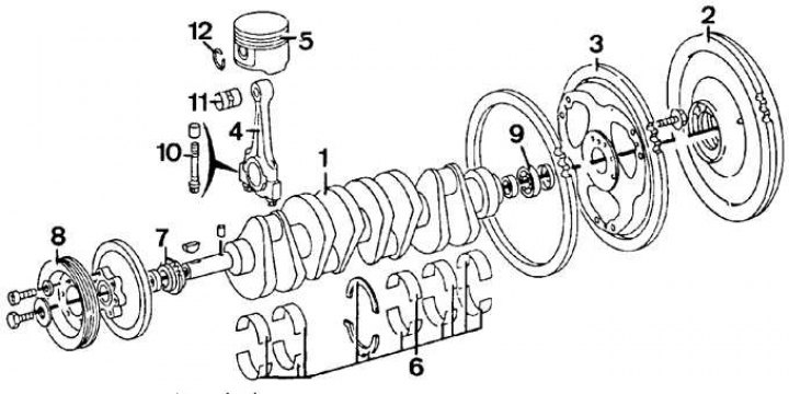
1 - crankshaft; 2 - flywheel (Manual Transmission); 3 - drive plate (Automatic transmission); 4 - connecting rod; 5 - piston; 6 - root bearings and thrust half rings; 7 - asterisk; 8 - pulley; 9 - bearing; 10 - bolt; 11 - piston pin; 12 - retaining ring
Crank mechanism of 4-cylinder diesel engine
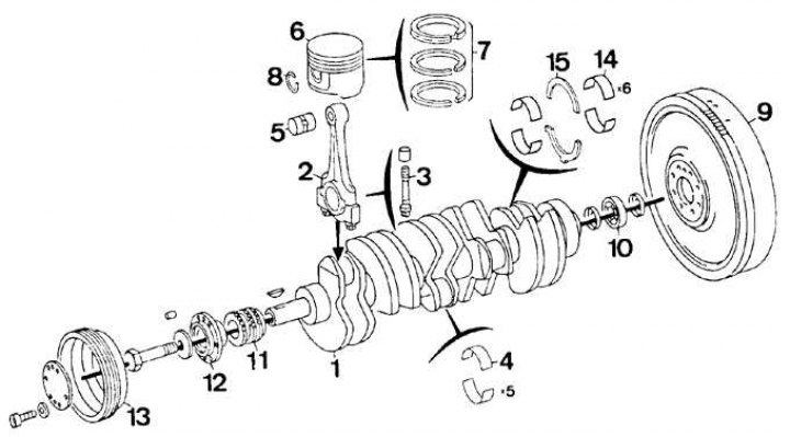
1 - crankshaft; 2 - connecting rod; 3 - bolt; 4 - connecting rod bearings; 5 - piston pin; 6 - piston; 7 - piston rings; 8 - retaining ring; 9 - flywheel; 10 - bearing; 11 - asterisk; 12 - hub; 13 - pulley; 14 - root bearings; 15 - persistent half rings
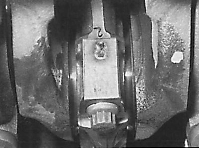
The location of the markings of the connecting rod and the bottom cover of the connecting rod
Piston head orientation mark
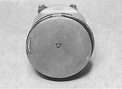
The orientation mark on the piston crown must point towards the drive chain.
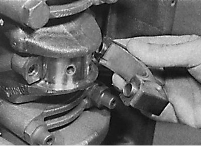
Removing the lower connecting rod cover
1. On 4-cylinder petrol engines, remove the cylinder head and oil pan.
2. On 6-cylinder SOHC gasoline engines, remove the cylinder head, oil pan and oil pump.
3. On 6-cylinder DOHC gasoline engines, remove the cylinder head, oil pan, oil pump, and oil catch plate.
4. On diesel engines, remove the cylinder head, oil pan, oil pump and oil catch plate.
5. On all models, if there is carbon on the top of the cylinder, remove it with a soft scraper. The presence of a step in the upper part of the cylinder indicates excessive wear of the cylinder and the need to bore the engine cylinders.
6. Check for markings on the connecting rods and connecting rod caps. Marking is located on the side of the intake manifold (see fig. The location of the markings of the connecting rod and the bottom cover of the connecting rod). If there is no marking, use a hammer and center punch or paint to mark the position of the connecting rod and connecting rod bottom cap.
7. Check for orientation marks on the piston crown. The arrow on the piston crown must point into the drive chain (see fig. Piston head orientation mark). Often the orientation mark is not visible due to the presence of soot, so the piston crown must first be cleaned. If there is no orientation mark on the piston head, use a scriber to apply it.
8. Rotate the engine crankshaft until pistons 1 and 4 (4-cylinder engines), 1 (5-cylinder engines), or 1 and 6 (6-cylinder engines) were set at bottom dead center.
9. Unscrew the bolts securing the cover of the lower head of the connecting rod of the first cylinder and remove the lower connecting rod cover (see fig. Removing the lower connecting rod cover).
10. Using a hammer handle, push the piston up the cylinder block and remove it from the cylinder block.
11. Install the connecting rod cover on the lower head of the connecting rod and screw it with bolts, which will allow you to keep them in a set and not confuse them.
12. Remove the piston of the fourth cylinder in the same way (4-cylinder engines) or 6th cylinder piston (six-cylinder engines).
13. Rotate the crankshaft to set the remaining pistons to bottom dead center and remove the pistons in the same manner.