



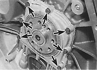
Location of the crankshaft rear cover mounting bolts on a 4-cylinder petrol engine
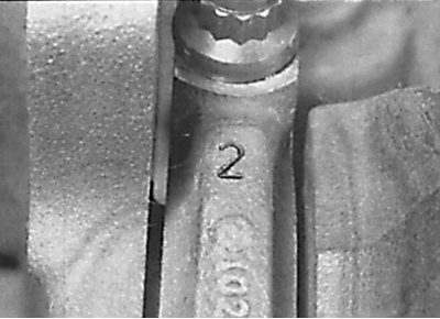
Location of identification mark on main bearing cap
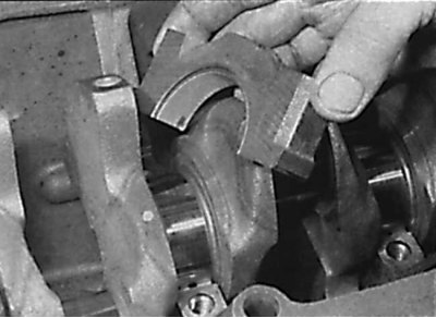
Removal the crankshaft main bearing cap
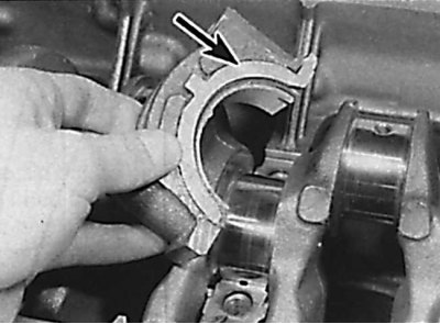
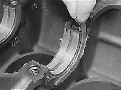
Removal the thrust half ring from the main bearing cap
Removal the upper thrust half rings from the engine cylinder block
1. On a 4-cylinder engine, remove the oil pan, timing chain cover, timing chain, and flywheel/drive plate. If necessary, also remove the crankshaft sprocket.
(Article was borrowed from the website MercedesMan)
2. On 6-cylinder SOHC gasoline engines, remove the oil pan, oil pump, lower timing chain cover, timing chain, and flywheel/drive plate. If necessary, also remove the crankshaft sprocket.
3. On DOHC 6-cylinder gasoline engines, remove the oil pan, oil pump, oil catch plate, lower timing chain cover, timing chain, and flywheel/timing plate. If necessary, also remove the crankshaft sprocket.
4. On diesel engines, remove the oil pan, oil pump, oil catch plate, timing chain cover, timing chain and flywheel/timing plate. If necessary, also remove the crankshaft sprocket.
5. Unscrew the bolts and remove the rear crankshaft cover from the cylinder block. Remove the gasket (see Fig. Location of the crankshaft rear cover mounting bolts on a 4-cylinder gasoline engine).
6. Remove the pistons and connecting rods. If you do not need to replace the pistons and connecting rods or piston rings, there is no need to remove the cylinder head and remove the pistons and connecting rods. In this case, install the pistons and connecting rods so that the connecting rods do not touch the crankshaft journals.
Caution: If pistons are located in cylinders with the cylinder head installed on the engine, be careful not to allow the pistons to strike the valves.
7. Check the crankshaft axial clearance.
8. Check for markings on the main bearing caps. If there are no markings, apply them. On 4-cylinder engines, the main bearing caps are marked with numbers from 1 to 5 from the drive chain. Similarly, on 5-cylinder engines, the caps are numbered with numbers from 1 to 6, and on 6-cylinder engines with numbers from 1 to 7 (see Fig. Location of identification mark on main bearing cap).
9. Unscrew the bolts and remove the main bearing caps with liners (see fig. Removing the crankshaft main bearing cap).
10. Mark the location and orientation of the oil pickup tube bracket, which is also secured with the main bearing cap bolts.
11. Remove the lower thrust half rings for adjusting the axial clearance of the crankshaft from both sides of the corresponding main bearing cap (see Fig. Removing the thrust half ring from the main bearing cap):
- on 4-cylinder engines from the cover of the central main bearing No.3;
- on 5-cylinder engines from the main bearing cap No.4;
– on 6-cylinder engines from the main bearing cap No.5.
12. Carefully remove the crankshaft.
13. Remove the upper main bearing shells from the cylinder block and stack them with the corresponding caps. Remove the upper thrust half rings (see fig. Removing the upper thrust half rings from the engine cylinder block).