
The pistons and cylinders of the engine are divided by size into six groups and are designated 0, 0+, 1, 1+, 2 and 2+. The group number is stamped next to the cylinder on the split surface of the cylinder block, as shown in fig. 26. The piston group number must always match the cylinder group number. Pistons of repair sizes are divided into three groups and are designated 0, 1 and 2.
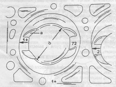
Pic. 26. View of the top side of the piston and cylinder block, d-diameter.
There is a recess in the piston head ("d" in fig. 27), the dimensions of which are different for different series of engines. When replacing pistons, always compare the bore diameters of the old and new pistons. The recess depth is also different for different engine series. The shape and dimensions of the piston affect the compression ratio of the engine and therefore they are not interchangeable for different engine series.
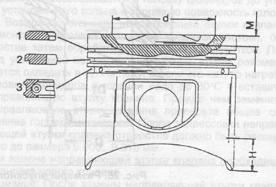
Pic. 27. Piston section.
1 - top compression ring,
2 - lower compression ring,
3 - oil scraper ring with spring, d=52 mm (350 SE), d=66 mm (450 SE), M=1 mm (350 SE), M=5.9mm (450 SE),
H is the place where the piston diameter is measured.
Mark each piston and connecting rod with the number of the cylinder from which they are removed. It is better to do this with paint on the piston head and mark with an arrow the direction towards the front of the engine.
When disassembling the piston, mark the position of the connecting rod cap and the connecting rod, marking them with an arrow and the cylinder number. The designation can be applied with a center punch (1 notch - cylinder No. 1, etc.).
Mark the connecting rod bearings and connecting rod caps accordingly.
After removing the connecting rod cover and liners, remove the piston with the connecting rod by pushing it up. If necessary, clean the carbon deposits on the upper belt of the cylinder with a scraper.
Remove the circlips and use a drift to press the piston pin out of the piston.
Remove piston rings with pliers. If rings are to be reused, they must be marked. In the absence of pliers, metal strips can be used to remove the rings, which are inserted between the piston and the inner surface of the ring. The strip must protrude beyond the edge of the piston head to avoid damage to the cylindrical surface of the piston.