



Contents: Removal the engine ↡ Engine installation ↡
Removal the engine
It is recommended to remove the engine and gearbox together as a single power unit and then disconnect the engine from the gearbox. The following work is performed the same for all engine types, additional instructions are given for cars with an automatic transmission. When lifting the power unit, it must be tilted at an angle of 45° to ensure exit from the engine compartment of the gearbox. The power unit weighs more than 200 kg, so when removing it, special care must be taken not to damage the body surfaces or paintwork.
- To avoid damage, place protective covers on the vehicle fenders. Release the locking lever on the left hood bracket and lift the hood up until the lever disengages. Then release the locking lever on the right hood bracket. Move the hood to a vertical position. Fig. 9 shows the position of the latch.
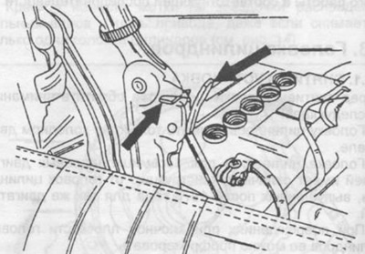
Fig. 9. Open the hood to a 90° angle.
- Disconnect the negative cable from the battery and remove the battery together with the mounting frame.
- Open the cooling system cap. The coolant temperature should not be more than 90°C
- Loosen the coolant drain plugs on the right and left sides of the cylinder block. Do not confuse the plugs with the crankshaft main bearing cap mounting bolts. Fig. 10 and 11 show the coolant drain plugs and the arrows indicate the cap mounting bolts.
- Remove the radiator and fan. To do this, remove the rubber supports and radiator mounting brackets. Remove the radiator, then remove the oil cooler. In cars with an automatic transmission, before removing the radiator, remove the hoses from the transmission oil cooling radiator and plug the holes in the hoses.
- Remove the expansion tank.
- Remove the exhaust system assembly.
- Suck the oil out of the power steering reservoir and disconnect the hoses from the power steering pump.
- Disconnect all hoses and pipes of the cooling system, lubrication system, fuel system and wires between the car body and the engine. It is advisable to mark the pipes.
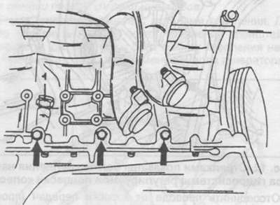
Fig. 10. Location of the coolant drain plug (1) on the left side of the cylinder block. Do not unscrew the bolts indicated by the arrows.
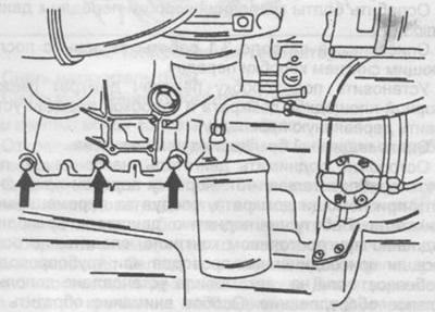
Fig. 11. Location of the coolant drain plug on the right side of the cylinder block. Do not remove the bolts indicated by the arrows.
- Disconnect the fuel supply control rod.
- In cars with air conditioning, it is necessary to drain the refrigerant. The work must be carried out very carefully. If you do not have experience, you must seek technical assistance and instructions. Then disconnect the hoses from the dual pipeline.
- Unscrew the bolts securing the front engine mounts at the bottom of the body on the left and right; use an extension with a hinge that is inserted from below to unscrew them.
- Attach a lifting cable to the engine and place it on the hook of a crane or other lifting device. Pull the cable slightly taut.
- In vehicles with adjustable wheel suspension, unscrew the four bolts securing the hydraulic suspension pump together with the connecting pipes, remove the pump and set it aside (see fig. 12). Remove the pump drive parts.
- Remove the rear engine mount cross member together with the support; before removing, mark the position of the cross member relative to the body.
- Disconnect the propeller shaft from the gearbox and move it back. Do not loosen the clamping nut on the propeller shaft. Section 11 provides further instructions on this work.
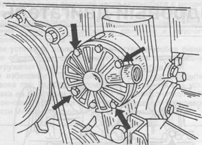
Fig. 12. The arrows show the mounting bolts for the adjustable wheel suspension hydraulic system pump.
- Disconnect the wires from the gearbox (reverse light switch wire). In automatic transmissions, disconnect the Kickdown device wires. Unscrew one side of the steering shock absorber mount and rotate it.
- Remove the engine mount shock absorbers.
- Loosen the gearbox-to-engine mounting bolts.
- Described in section 3.1 the work involves subsequent removal of the gearbox.
- Place a jack under the gearbox (place a wooden spacer between the jack support platform and the gearbox).
- Remove the protective mudguard of the body tunnel.
- Carefully lift the engine, tilting it at an angle of approximately 45°. Raise the gearbox using a jack, following the movement of the engine. Carry out the work of lifting the engine slowly, constantly checking to see if there are any attached wires or pipes left, especially if the car is equipped with additional equipment. Pay special attention to the cable fastening.
Engine installation
The engine is installed in the reverse order, observing the following points:
- Do not install units on the engine until it is installed on the mounting supports and the cable is freely sagging. Check the position of the engine supports and tighten the mounting bolts to a tightening torque of 30 Nm.
- Tighten the coolant drain plugs.
- Connect the cardan shaft.
- Check the ignition timing.
- Check the engine for leaks.
- Remove oils and greases from rubber parts.
- Tighten all bolts and nuts to the required tightening torque (see section 19).
- Check the freezing point of the drained coolant and if it meets the norm, it can be reused.
- Check the cooling system together with the coolant pump for leaks (section 5.2.1).
- Check the air filter element for contamination and install it.
- Check the idle speed and CO content in the exhaust gases and adjust if necessary.
An indication. If necessary, replace the rubber parts of the engine suspension, (removing the engine and gearbox is not required see section 2.13).