
Checking the radiator cap and radiator
The cooling system operates under excess pressure. The radiator cap contains a valve with a spring that closes the cooling system. When the pressure rises to 1.0 bar, the valve opens and the cooling system communicates with the environment. The cap is labeled 100 (1.0 bar). Excessive pressure in the cooling system raises the boiling point of the coolant.
To check the opening pressure of the valve in the plug, a special pump is needed. The plug is attached to the pump and, by increasing the pressure by the pump, the value of the valve opening pressure is determined. This value must be within the above data. If it deviates from the specified value, the plug must be replaced. The same device checks the tightness of the cooling system. The pump is mounted on the radiator neck and an overpressure of 1.5 bar is created in the system, and the pressure drop is checked on the pressure gauge. In a healthy cooling system, a pressure of 1.5 bar must be maintained for at least 5 minutes. If the system is leaking, check all connections and identify leaks by traces of coolant.
Removal and installation of a radiator
To remove the radiator, do the following:
Drain the coolant as described in section 5.1.1.
Loosen the clamps and disconnect the upper and lower hoses.
On vehicles with an oil cooler and gearbox cooler, also close off the inlet and outlet hoses and remove them. In 8-cylinder engines, close the gearbox radiator hoses and shut off the pipeline from the oil cooler.
Remove the spring clips on the top side of the heatsink, lift up the fan shroud and hang it on the fan.
On the 280, remove the oil cooler bolt, pull the cooler up out of the radiator guide and set aside.
Remove the two spring clips located next to the hood hinge and raise the radiator. Check cooling system hoses and replace if necessary.
Installation is carried out in the reverse order. The mounting pins must fit freely into the rubber mounts on the cross member. Adjust the position of the fan shroud as described below. Screw in and tighten the drain plugs on the cylinder block to 30 Nm for the six-cylinder engine and 25 Nm for the eight-cylinder engine. Tighten the oil cooler hoses to 25 Nm, tighten the union nuts of the gearbox radiator hoses to 15 Nm, fan cowl to 2.5 Nm.
Pour coolant into the cooling system. as described in section 5.1.
Fan shroud adjustment
Fan shrouds with a slight gap with the fans are installed as standard on cars. Therefore, when installing the shroud, fine adjustment is required to avoid contact with the fan when the motor is moved, which can lead to shroud breakage. The mounting holes of the fan shroud allow you to adjust its position, both in height (size A), as well as in width (size B) (see fig. 110). For six-cylinder engine size "A" 25mm and size "IN" 15 mm; for eight-cylinder engine size "A" 20mm and size "IN" 15 mm. Distance between heatsink surface and fan (size "A") should be 31 mm. After adjusting the position of the fan shroud, tighten the mounting bolts.
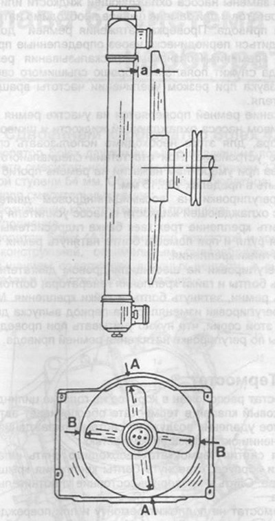
Pic. 110. Table of adjusting dimensions.
a=31 mm, A=25 mm 280 S/SE, 20 mm 350 SE/450 SE, B=15