



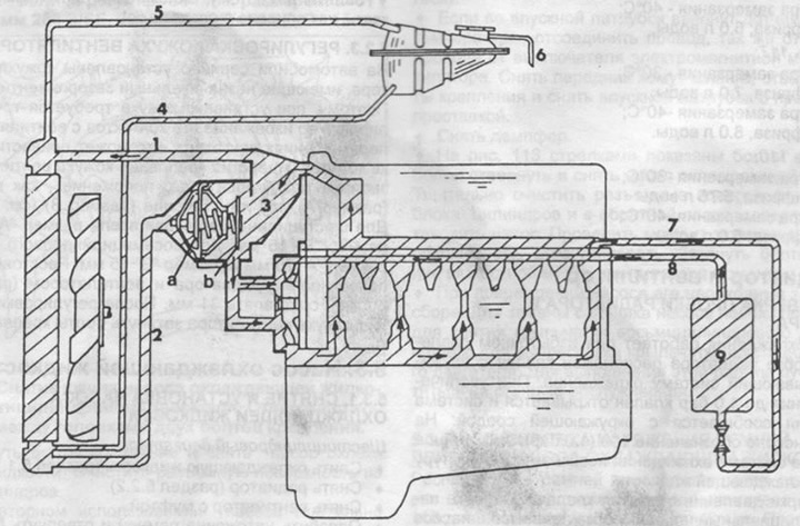
Fig. 108. Cooling diagram of a six-cylinder engine.
1 - from engine to radiator,
2 - from the radiator to the thermostat,
3 - bypass,
4 - from the distribution tank to the radiator,
5 - gas outlet pipeline,
6 - drain hose,
7 - from the cylinder head (intake manifold left),
8 - from the body heater,
9 - body heater.
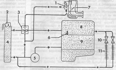
Fig. 109. Schematic diagram of the cooling system of eight-cylinder engines.
1 - heater, starting automation,
2 - radiator cap,
3 - thermostat,
4 - radiator,
5 - coolant pump,
6 - temperature indicator sensor,
7 - carburetor,
8 - cylinder head,
9 - cylinder block,
10 - body heater tap,
11 - body heater.
The coolant pump is mounted on the cylinder block and sealed with a seal. The cooling system is closed, which increases the boiling point of water to +118°C. When using antifreeze with a freezing point of -30°C, the boiling point increases to +125°C. When driving at full load, in mountainous conditions, in a column, on highways with long climbs or in an area with high ambient temperatures, the coolant temperature gauge can approach the red mark without adversely affecting engine operation. When driving on long descents in cars with an automatic transmission, the gearbox control lever can be set to position N for better cooling of the oil in the gearbox. The electromagnetic clutch of the fan is switched on and off depending on the coolant temperature. The fan turns on at a temperature above +100°C and turns off at +95°C.
Article obtained from this portal MercedesMan.ru