
The measurement is made in the longitudinal and transverse directions along three belts located 10 mm below the top surface of the cylinder, 10 mm above the bottom surface of the cylinder and in the middle of the cylinder. Thus, 6 measurements are made on each cylinder, which are indicated by the numbers 1... 3 and the letters A and B and are shown in Fig. 28. The measurement results must be recorded and compared with the data in the tables. If deviations from the tabular data are noted in at least one cylinder, all cylinders of the block are bored. Permissible deviation from the nominal value is not more than 0.05 mm. oversized pistons (0.5 mm and 1 mm), as already mentioned, are divided into size groups. The final size of the cylinder is determined after measuring the piston diameter, which is measured along the belt located 10 mm above the lower edge of the piston skirt, to this size it is necessary to add the value of 0.02... 0.03 mm of the gap between the cylinder and the piston. In addition, it is necessary to take into account the allowance of 0.05 mm for uneven processing along the height of the cylinder. As a result, the deviation of the cylinder diameter from the nominal value should not exceed 0.08 mm. To check the clearance between the piston and the cylinder, it is necessary to measure as described above and calculate the difference in the dimensions of the piston and cylinder. If the result exceeds 0.08 mm, the cylinder must be bored, because its dimensions are on the border of admissible wear.
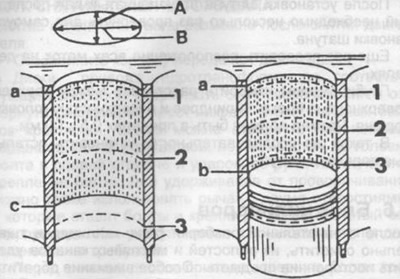
Pic. 28. Cylinder measurements. The measurement bands are labeled 1, 2 and 3.
Measurement directions: longitudinal "A", transverse "IN",
a - piston TDC,
b - BDC,
c - lower position of the piston skirt.