



- The crankshaft rotates in five main bearings. The main bearing caps are secured with four studs and nuts. The three middle caps are additionally secured with side bolts screwed in from the outside of the block. Do not confuse these bolts with the drain plugs of the cooling system (see fig. 35).
- The main bearing caps are processed together with the cylinder block and are not supplied as spare parts.
- To secure the main bearing caps, studs with self-locking threads are used, screwed into the cylinder block. The studs are used once and are subject to replacement after unscrewing. The outer studs are offset by 2 mm relative to the inner ones, which ensures a strictly defined position of the cap relative to the cylinder block.
- The bolts and nuts securing the main bearing caps must be tightened in a specific sequence.
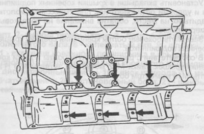
Fig. 35. The arrows show the locations of the bolts for fastening the center main bearing caps.
Removal the crankshaft
Removal of the crankshaft is possible after removing the engine.
Disconnect the gearbox from the engine.
The torque converter drive discs are held in place in an appropriate manner to prevent them from turning and the 8 special mounting bolts are unscrewed evenly crosswise. The bolts can be unscrewed using a socket wrench with a handle, placing the wrench on the bolt head on the right side and hitting the handle to loosen the bolt. To prevent them from turning, you can also use a lever with two holes, into which the bolts are placed and the lever is secured to the drive gear ring. As already mentioned, there is no need to apply marks for installation.
Before removing the drive discs, unscrew the pulley and damper mounting bolts at the front end of the crankshaft.
Remove the cylinder heads together with the intake and exhaust manifolds (section 2.3.1).
Remove the camshaft drive cover.
Unscrew the oil pan (section 4.2).
Remove the pistons as described in section 2.5.1.
Install a dial indicator on a bracket secured to the front of the cylinder block so that the tip of the indicator rests against the end of the crankshaft (see fig. 33). Use a screwdriver to move the crankshaft to the stop in one direction, set the indicator scale to "0". Move the crankshaft to the stop in the other direction and note the readings on the indicator scale. This value corresponds to the axial clearance and should be recorded for subsequent assembly. If the clearance is more than 0.30 mm, then during subsequent assembly it is necessary to install wider liners in the middle main bearing.
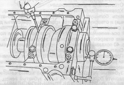
Fig. 33. Measuring the axial clearance of the crankshaft.
Loosen the bolts and carefully remove the oil seal flange at the rear of the cylinder block.
Loosen the nuts of the main bearing caps crosswise evenly, check the cap numbers. Cap No.1 is on the drive pulley side. The cap numbers are in the middle part.
Unscrew the cover mounting bolts on each side of the block, shown in Fig. 35.
Remove the covers with liners. Mark all liners on the outside with the bearing number (do not scratch or punch).
Carefully remove the crankshaft from the cylinder block.
Remove the liners and store them together with the lid liners and lids.