
Install the liners in the holes of the main bearings, aligning the holes for the oil supply and the grooves for attaching the liners. Lubricate the liners.
Install the middle main bearing shell with thrust flange.
Carefully install the crankshaft onto the main bearings in the cylinder block.
Install the liners in the main bearing caps and tap them into place with the blows of a rubber or plastic hammer, paying attention to the serial numbers of the caps.
Tighten the side bolts of the middle main bearing caps.
In accordance with fig. 36 Tighten the bolts and nuts for fastening the covers: M12 nuts with a tightening torque of 100 Nm, M10 bolts with a torque of 65 Nm.
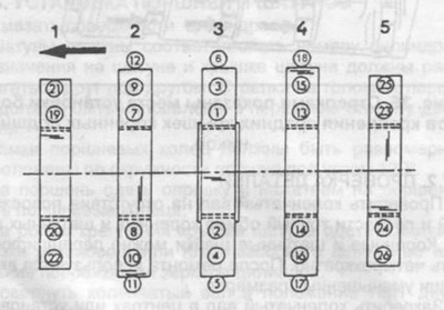
Pic. 36. The procedure for tightening the nuts and bolts of the main bearing caps.
Rotate the crankshaft several times.
Check again the axial clearance determined when removing the crankshaft. If the clearance is increased, carry out the above operations.
To measure an axial backlash of lower heads of rods, as it is shown in fig. 37. A gap of more than 0.5 mm is not allowed, and it is necessary to re-disassemble.
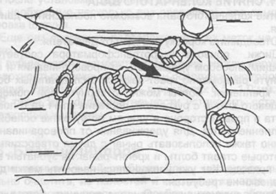
Pic. 37. Measurement of the axial clearance of the connecting rod bearings on the crankshaft journal. The location of the probe is shown by an arrow.
Install pistons and connecting rods as described in section 2.5.5.
Install the rear seal cover.
Install the camshaft drive (section 2.10).
Install box drive discs (section 2.7.4).
Install oil pump (see section 4.1.1).
Install oil sump (section 4.2).
Carry out the rest of the work in reverse order.