



- wipe the crankshaft main bearing seats and insert the liners with holes and grooves for supplying oil into them so that the guide protrusions fit into the recesses provided for them in the bearing seats. Lubricate the bearings generously;
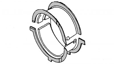
Figure 81. Installing half rings that adjust the axial clearance of the crankshaft
- install adjusting half rings on the corresponding main bearing to regulate the axial clearance of the crankshaft.
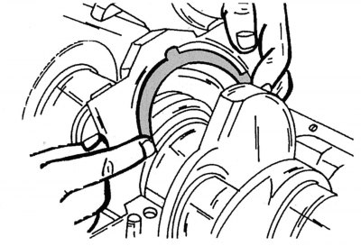
Figure 82. Installing the main bearing cap together with the thrust half ring for adjusting the crankshaft axial clearance
These half rings with protrusions resting on the cylinder block socket and the main bearing cap are absolutely identical, so they should be installed as shown in the figure 81. The protrusions on the half rings serve to prevent them from turning. The oil grooves must be directed towards the crankshaft flange as shown in the figure 82.
- carefully lower the crankshaft into the bearing seats with the liners. If the connecting rods with pistons were not removed from the cylinder block, place the connecting rod bases with liners on the connecting rod journals of the crankshaft;
- place the lower bearing shells into the main bearing caps and generously lubricate their working surfaces;
- place the thrust half rings for adjusting the axial clearance of the crankshaft into the grooves of the middle main bearing cover. The oil grooves should be on the outside (see figure 82). Holding the half rings on the right and left sides with your fingers to prevent them from falling out, install the cover on the corresponding main bearing stand;
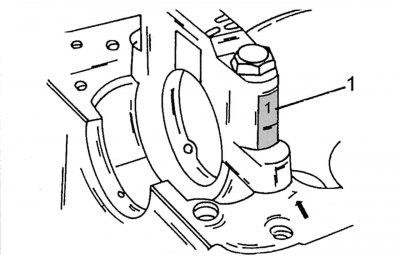
Figure 83. Marking (1) of main bearing caps
- install the remaining main bearing caps into their seats in the engine crankcase and tap them from above with a rubber or plastic hammer. Bearing caps must be installed in accordance with their digital markings. For example: a number stamped on the crankcase next to the bearing stand indicates that a bearing cap with the digital marking "1" should be installed on this bearing stand (figure 83). Therefore, the numbers stamped next to the crankshaft main bearing posts must match the numbers on the bearing caps;
- tightening of the main bearing cap bolts should be carried out in several stages, starting from the middle of the crankshaft and moving towards its edges, finally tightening with a torque of 55 N·m. After this, in the same way, finally tighten these bolts by another 90–100°;
- turn the crankshaft several times to identify possible jamming points;
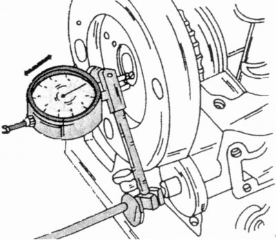
Figure 73. Checking the crankshaft axial clearance
- check the crankshaft axial clearance again using the method described in subsection. "Removal the crankshaft", with reference to the drawing 73;
- install pistons with connecting rods taking into account the instructions contained in subsection 2.6.6;
- install the rear crankshaft oil seal cover;
- install the camshaft drive mechanism (subsection 2.12.2);
- install flywheel (subsection 2.8.4);
- secure the clutch to the flywheel, taking into account the markings. The driven disk must be centered;
- install oil pump (see the corresponding subsection.).
All remaining work must be performed in the reverse order of removal until the engine is fully assembled and ready for installation on the vehicle.