
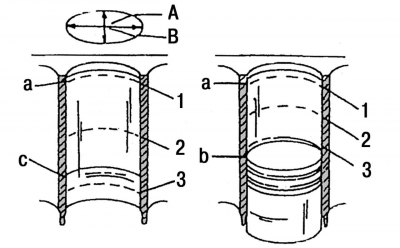
Pic. 55. Places for measuring the holes of cylinder liners: A - measurement in the longitudinal axis of the engine; B - measurement in the transverse axis of the engine; a - the upper stopping point of the upper piston ring; b is the lower stopping point of the piston; c - lower stop point of the oil scraper ring; 1, 2, 3 - measuring points
Using an inside gauge, measure the cylinder diameter as shown in fig. 55.
Measurements are taken in the longitudinal and transverse axes of the engine block and at equal depths of the cylinders. All six results are neatly recorded. The difference in the obtained results of measurements in the upper and lower parts of the cylinder indicates its taper. The difference in the results obtained when measuring in the longitudinal axis and when measuring in the transverse axis indicates the ovality of the cylinder bores. At none of the 6 measuring points, the cylinder diameter should deviate from the specified one by more than 0.12 mm.
For each engine, replaceable cylinder liners are provided, which must be pressed into the cylinder block at a service station. The mating surface of the cylinder block must be checked for deformations in the same way as the mating surface of the cylinder head. Take measurements in the longitudinal, transverse and diagonal directions under the ruler installed on the mating surface of the cylinder block. A feeler gauge with a thickness of more than 0.10 mm should not pass under the ruler at any point on the surface.