
- disconnect the gearbox from the engine. When removing the gearbox, take care not to bend its input shaft;
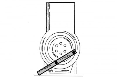
Pic. 72. Fixing the flywheel from turning
- secure the flywheel against turning and unscrew the clutch mounting bolts crosswise. Sometimes these bolts are loosened without fixing the flywheel using a socket hex wrench. To do this, put the auxiliary lever on the key handle and, holding the key in the bolt head with one hand, hit the upper end of the auxiliary lever with the other hand. In most cases, bolts turn away from such blows to the key. To fix the flywheel, you can use a piece of metal strip drilled at two points and fixed to the flywheel with two bolts, as shown in fig. 72. After completing this operation, you can unscrew all the remaining flywheel mounting bolts in order. Before removing the clutch, it is necessary to make a mark on the pressure plate and flywheel with a center punch in order to install the parts in the same position during subsequent assembly. Without removing the latch from the flywheel, unscrew the bolt securing the belt pulley at the opposite end of the crankshaft, from the front of the engine. The dismantling of the drive disk of an automatic transmission is carried out in the same way;
- remove the cylinder head, taking into account the previously stated instructions;
- remove the cover of the camshaft drive mechanism (see subsection 2.5);
- remove the crankcase oil pan;
- when removing only the crankshaft, the pistons with connecting rods can remain inside the cylinder block. Otherwise, remove the pistons and connecting rods according to the instructions in subsection 2.6.1. If the pistons and connecting rods remain inside the engine, then when removing the bearing caps and liners, do not forget to mark their belonging to specific connecting rods and relative to each other;
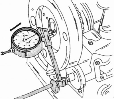
Pic. 73. Checking the axial clearance of the crankshaft
- from the side of the front end of the cylinder block, install a measuring indicator on a tripod so that its probe lies on the crankshaft flange, as shown in Fig. 73. Using a screwdriver, push the crankshaft to one side, bring the indicator probe to the pin and set the indicator pointer scale to zero. Then, on the other hand, push the crankshaft in the opposite direction and record the indicator readings. The axial clearance of the crankshaft thus established must be maintained during its subsequent assembly. If it exceeds the value of 0.30 mm, then this must be taken into account during subsequent installation. The middle main bearing of the crankshaft is equipped with adjusting thrust half rings, two pieces on each side, to compensate for axial clearance. If the gap becomes too large, then new half rings can be installed, but always of the same thickness on both sides;
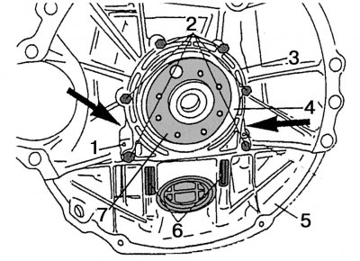
Pic. 74. The rear of the engine crankcase: 1 - spring tension pin; 2 - M6x22 mm bolts for fastening the crankshaft rear cuff holder; 3 — the holder of a back cuff of a cranked shaft; 4 — a back cuff of a cranked shaft; 5 - oil pan; 6 - bolt M6x85 mm; 7 - rear flange of the crankshaft
- unscrew the bolts of the holder of the rear collar of the crankshaft and carefully separate it from the cylinder block. Its attachment is shown in Fig. 74;
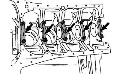
Pic. 75. Places for applying digital marking of the caps of the main bearings of the crankshaft
- evenly, crosswise unscrew the mounting bolts and remove the crankshaft bearing caps. Make sure the bearing cap numbers are clearly visible. They are numbered sequentially from 1 to 5. Cover No. 1 is located on the side of the belt pulley. The marking is applied in the middle part of the bearing caps (pic. 75);
- remove the crankshaft bearing shells and put them next to their covers. All liners also have a digital marking applied on the back and indicating the bearing number;
- carefully lift the crankshaft off the cylinder block;
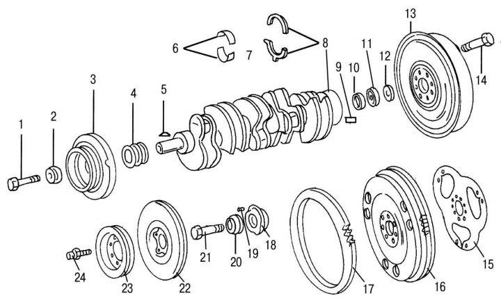
Pic. 76. Crankshaft and mating parts on the example of the 602 engine (similar parts are used on the 601st engine): 1 — a bolt of fastening of an asterisk of a chain drive on a cranked shaft; 2 — a washer of a bolt of fastening of an asterisk of a chain drive; 3 - torsional vibration damper (if it is installed); 4 - twin drive sprocket; 5 - key; 6 - bearing shells of the crankshaft; 7 - crankshaft; 8 - adjusting thrust half rings, 5 size groups; 9 - landing pin; 10 - remote washer; 11 - radial ball bearing; 12 - washer; 13 - combined two-mass flywheel; 14 - flywheel mounting bolt; 15 - locking plate; 16 - flywheel, standard version; 17 - gear ring of the flywheel; 18 - vibration damper hub (if it is installed); 19 - locating pin; 20 - washer; 21 — a bolt of fastening of a vibration damper / a belt pulley to a nave (if it is installed); 22 - vibration damper hub (if it is installed); 23 - belt pulley (if it is installed); 24 — a bolt of fastening of a vibration damper and a belt pulley
- remove the liners remaining in the cylinder block seats and arrange them next to the corresponding liners and crankshaft bearing caps. These liners have holes and grooves for supplying oil to the crankshaft journals, and during subsequent assembly they are installed first in the sockets of the cylinder block. On fig. 76 shows the details of the crankshaft and bearings, with the exception of the main bearing caps.