
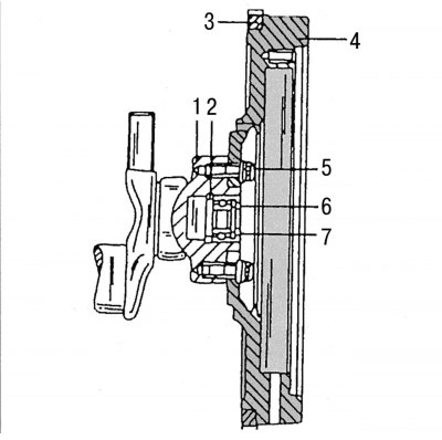
Pic. 84. Flywheel design (models with manual transmission): 1 - crankshaft flange; 2 - remote ring; 3 - ring gear for starting the engine with a starter; 4 - flywheel; 5 - malleable bolts M10x22 mm; 6 - ball bearing; 7 - retaining ring
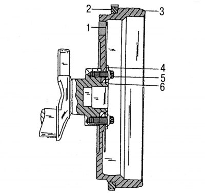
Pic. 85. The design of the flywheel on vehicles with automatic transmission: 1 - driving disk of the torque converter; 2 - ring gear for starting the engine with a starter; 3 - flywheel; 4 - remote washer; 5 - malleable bolt; 6 - crankshaft
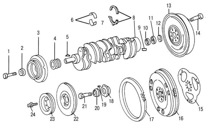
Pic. 76. Crankshaft and mating parts on the example of the 602 engine (similar parts are used on the 601st engine): 1 — a bolt of fastening of an asterisk of a chain drive on a cranked shaft; 2 — a washer of a bolt of fastening of an asterisk of a chain drive; 3 - torsional vibration damper (if it is installed); 4 - twin drive sprocket; 5 - key; 6 - bearing shells of the crankshaft; 7 - crankshaft; 8 - adjusting thrust half rings, 5 size groups; 9 - landing pin; 10 - remote washer; 11 - radial ball bearing; 12 - washer; 13 - combined two-mass flywheel; 14 - flywheel mounting bolt; 15 - locking plate; 16 - flywheel, standard version; 17 - gear ring of the flywheel; 18 - vibration damper hub (if it is installed); 19 - locating pin; 20 - washer; 21 — a bolt of fastening of a vibration damper / a belt pulley to a nave (if it is installed); 22 - vibration damper hub (if it is installed); 23 - belt pulley (if it is installed); 24 — a bolt of fastening of a vibration damper and a belt pulley
Before replacing the flywheel, its height should be measured in order to get a new flywheel of the same design. On fig. 84 and 85 show the flywheels in question. On fig. 76 also shows the shape of the flywheel and drive plate.
The flywheel or drive disk, together with the ring gear for starting the engine from the starter, can be changed without subsequent balancing of the crankshaft. The ring gear of the drive disc or flywheel can also be replaced with a new one, and although this work is best done in a workshop, the following is a description of how to perform this work. There is no need to remove the engine before doing this.
To remove the combined flywheel, perform the following steps:
- remove the gearbox;
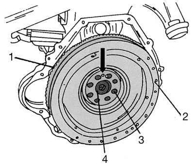
Pic. 86. Mounting the flywheel on the crankshaft (the arrow shows the centering hole): 1 - ring gear; 2 - flywheel; 3 - malleable bolts M10x22 mm; 4 - ball bearing
- while holding the flywheel from turning with a screwdriver inserted between the teeth of the ring gear, or a bolt inserted into the cylinder block flange hole, unscrew all eight flywheel bolts in order. When reinstalling the flywheel or drive plate, make sure that the hole drilled in the flywheel between the two bolts and the hole in the crankshaft flange are always opposite each other. On fig. 86 shows the location of such a hole. A similar hole is made on the drive disk;
- remove the flywheel or drive disc. Distance washers are installed under the drive disk, which are also released after unscrewing the bolts;
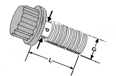
Pic. 87. Main dimensions for checking the condition of flexible bolts: L is the length of the bolt; d is the diameter of the pliable part of the bolt; D - diameter of the threaded part of the bolt
- measure the diameter of the thin part of the bolts. If the result of measurement on any of the bolts is less than 8.1 mm, then this bolt should be replaced. Measurements are taken as shown in Fig. 87;
- check the condition of the flywheel and replace the ring gear. If there are signs of wear or burns on the flywheel, it should be refurbished. At a specialized service station of Mercedes-Benz, there is all the necessary data for measurements and control. To replace the ring gear, a heating device with a temperature control range of up to 220°C is required.
The flywheel ring gear must be replaced in the following sequence:
- mark the position of the ring gear on the flywheel and clamp the flywheel in a vise;
- between the two teeth of the crown, drill a hole to the flywheel, but without cutting into the flywheel with a drill;
- using a chisel, chop off the old ring gear;
Attention! Protect your eyes from possible fragments when working with the flywheel.
- thoroughly clean the landing site of the crown on the flywheel;
- warm up the new crown to the specified temperature (see above) and quickly use pliers to put on the flywheel. Use a soft metal mandrel and a hammer to correct the position of the crown on the flywheel. This work must be done very quickly.
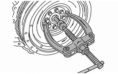
Pic. 88. Pressing out the ball bearing of the crankshaft
To replace the ring gear on the drive disk, the ring gear together with the steel ring must be dismantled from the drive disk. During subsequent assembly, install a new part in such a way that all the holes for the fixing bolts of the ring gear and the torque converter on the steel ring and on the drive disk coincide.
A ball bearing is mounted on the crankshaft flange. On vehicles with manual transmission behind this bearing 6 (see fig. 84) a safety ring 7 is pressed in, which is closed on both sides with washers made of Viton synthetic material for protection. Behind the bearing is a spacer. To press the bearing together with the retaining ring, use the puller shown in fig. 88.
If the bearing is removed, then it is necessary to press the retaining ring on the engine under the manual transmission.
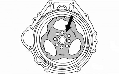
Pic. 89. Location of the centering hole on the drive disc
The installation of the flywheel or drive disk must be carried out as follows:
- attach the flywheel or drive plate to the crankshaft flange and turn it until the centering holes are against each other. When mounting the flywheel, refer to fig. 86, and when mounting the drive disk - to fig. 89, which shows the location of the centering holes. When installing the drive disk, a protective disk should be placed on it;
- screw the fixing bolts and tighten them to a torque of 30–40 Nm. You will need an Allen wrench to tighten these bolts. Tighten the bolts finally by another 90–100°, which corresponds to about 1/4 turn. The required tightening angle must always be maintained in order to take advantage of the elastic action of the flexible bolts.