



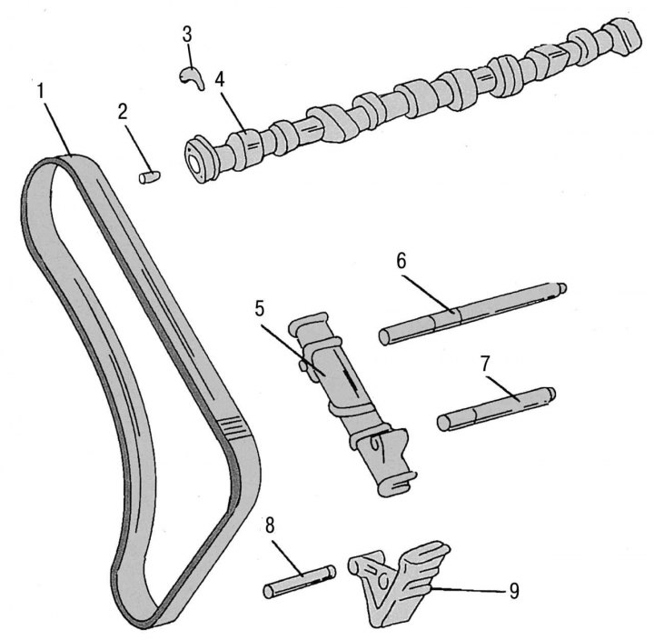
Figure 95 b. Other parts of the camshaft drive mechanism: 1 - double row drive chain; 2 - landing pin; 3 - camshaft thrust washer; 4 — camshaft; 5 - chain tensioner bars; 6 — support pin of the chain guide on the cylinder block; 7 — chain guide support pin; 8 — landing pin; 9 - chain guide groove
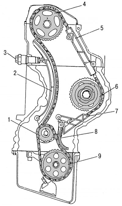
Figure 96. Camshaft drive mechanism assembly: 1 - crankshaft sprocket; 2 - chain tension shoe; 3 - chain tensioner; 4 — camshaft drive sprocket; 5 - chain tensioner; 6 — fuel pump drive sprocket; 7 - chain tensioner; 8 — oil pump drive chain tensioner lever; 9 — oil pump drive sprocket
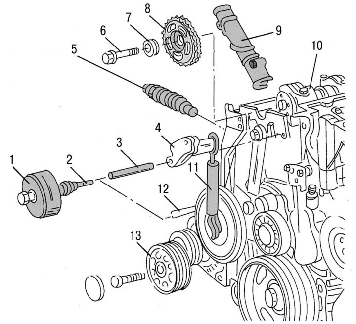
Figure 101. Details of the camshaft drive chain guide: 1 - puller; 2 - threaded pin for dismantling; 3 - upper support finger; 4 — tension spring lever; 5 - chain tensioner; 6 - flexible bolt, 25 Nm + 90°; 7 — camshaft drive sprocket washer; 8 — camshaft drive sprocket; 9 — drive chain damper; 10 — camshaft; 11 - tension spring; 12 - lower support finger; 13 - guide belt pulley
The location of the drive chain dampers is shown in the figure 95 b and 96. When removing them, a hammer is usually required to remove the support pins. The support pin has an M6 thread on the inside. Using a long M6 bolt, a bushing and a washer, this pin can be removed quite easily. Figure 101 shows the front of the engine with some details of installation and removal. When dismantling the upper drive chain guide (in the cylinder head) you need to proceed as follows (it is assumed that all parts that impede access to the parts to be removed have already been removed from the vehicle):
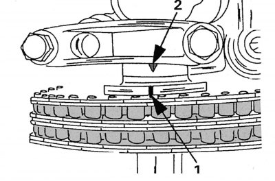
Figure 102. Location of marks when the piston of the first cylinder is at TDC
- remove the cylinder head cover. Before subsequent installation of the cylinder head cover, it is necessary to check the alignment of the TDC marks on flange 1 (figure 102) and on the cover 2 of the first camshaft bearing;
- remove viscous coupling;
- completely remove the drive belt tensioner. Tensioner Lever Support Pin 4 (see figure 101) the belt tensioner is also the support for the drive chain damper;
- remove the camshaft drive sprocket following the instructions contained in the relevant chapter;
- remove the chain tensioner (subsection 2.12.1);
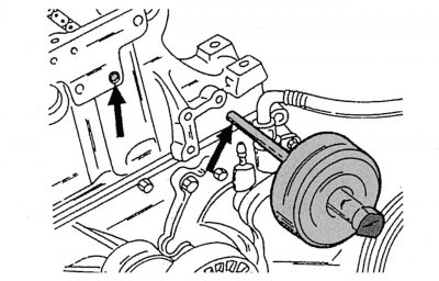
Figure 103. Removing the support pins (shown by arrows)
- remove both chain guide support pins using a hammer and a threaded insert (figure 103) and remove the chain guide from the top. If you don't have a knockout hammer, which is quite common, put a large washer on the support pin and a bushing on top. Then take a long M6 bolt with a large washer and screw it into the end of the support pin (the bolt washer should rest against the top edge of the bushing). When the bolt is subsequently tightened and the bushing is clamped, the support pin is released from the seat;
- before installing a new or previously used support pin, it is necessary to apply sealant to the flange;
- install the chain guide in the correct position and press the support pins into their mounting sockets. To prevent the chain guide from being squeezed out, a screwdriver is pressed against it to exert counter pressure. The guide groove in the chain guide support hole should fit onto the protrusion of the upper support pin;
- further assembly is carried out in the reverse order of disassembly.
When installing the drive chain onto the camshaft drive sprocket, pay attention to the paint marks.
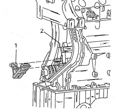
Figure 104. Installing the chain guide bar (1) on two support pins (2)
When replacing the lower chain guide bar, the location of which is shown in the figure 104, you need to perform the following operations:
- disassemble the front of the car to provide access to all necessary engine components and parts;
- remove the camshaft drive mechanism cover (see subsection 2.5.1);
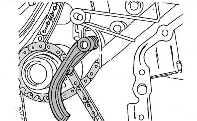
Figure 105. Removing the tension lever
- move the tension lever together with the spring and the chain pressure shoe back enough so that it can pass the chain and drop down onto the crankshaft, as shown in the figure 105;
- remove the tension lever from the support pin and carefully move it towards the side where the spring is weakened, then, having unhooked the spring, remove the lever together with it;
- remove the chain guide bar from both support pins;
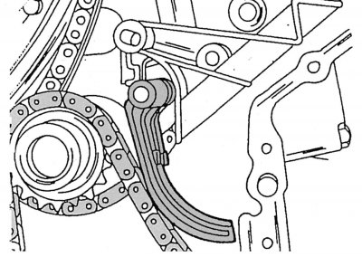
Figure 106. Correct position of the oil pump drive chain tensioner lever with pressure shoe
- insert a new chain guide bar onto the support pins. Hook the spring onto the chain pressure shoe and tension lever and push it all together onto the support pins as shown in the figure 106;
- install the camshaft drive mechanism cover in place following the instructions in subsection 2.5.