
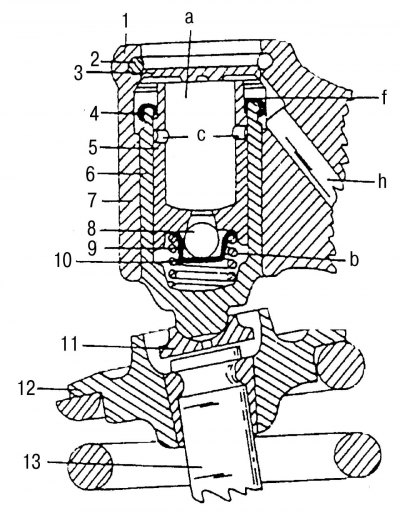
Pic. 114. Valve pusher: 1 - rocker; 2 - retaining ring; 3 - washer; 4 - cap; 5 - push rod; 6 - guide sleeve; 7 - guide channel of the ball; 8 - a ball with a diameter of 4 mm; 9, 10 - pressure springs; 11 - ball bearing; 12 - valve spring plate; 13 - valve; a - oil chamber; b - working chamber; c - leak return channels; f - annular groove; h - oil channel
The task of hydraulic valve lifters is to compensate for valve clearance, which changes as a result of thermal expansion and wear of parts of the valve timing system. The rocker arms are in constant contact with the camshaft, so noise from the valve train is kept low. Hydraulic compensators are installed in the rocker arms and act on the valves through the ball bearing 11 (pic. 114). The hydraulic valve clearance compensation system consists of the following main elements:
- pressure rod 5 with an oil chamber a and oil return channels with a check ball valve, parts 8, 9 and 10. The ball valve separates the oil chamber from the working chamber;
- guide sleeve 6 with working chamber b, pressure spring 9 and closing cap 4.
With the engine stopped, if the compensator is under constant camshaft lobe pressure, it can be completely unloaded (shrinks). The oil squeezed out of the working chamber b flows into the oil chamber and along the annular gap - along the gap between the guide sleeve and the pressure rod. When the top of the cam leaves the rocker, the pressure is removed from the pressure rod 5. Spring 9 moves the stem up until the rocker comes into contact with the cam. The vacuum created in the working chamber from the movement of the rod opens the ball valve, and oil can flow from the oil chamber into the working chamber. The ball valve closes as soon as the rocker rests on the cam, the pressure on the push rod begins to increase. The oil in the working chamber now acts as a rigid hydraulic connection, which opens the corresponding valve.
When the engine is running, depending on the engine speed and the position of the cam, the pressure rod is lowered by a small amount. The oil necessary for the operation of the compensators is supplied through the oil line running along the cylinder head, and then through the transverse channels leading to the bearing racks of the rocker arms. Further, from the bearing racks, oil is supplied to the rocker shaft, and from it through channel h in the rocker arm to the corresponding compensator. The oil supply to the oil chamber is carried out through the slotted washer 3. The amount of oil in the oil chamber a is always sufficient to fill the working chamber b in any operating conditions of the engine. Excess oil and air pockets (air bubbles in oil) can exit through the annular gap between the washer 3 and the rocker arm. Oil squeezed out of the working chamber flows down the annular gap (along the annular channel) between the guide sleeve and the pressure rod and then through the return channels to the oil chamber. When dismantling hydraulic pushers, remember the following points:
- hydraulic tappets should always be stored in an upright position with the open side up.
- after dismantling the hydraulic pusher (subsection 2.13.2) it should be marked with the number of the cylinder, the pusher well.