
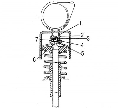
Pic. 116. Valve with hydraulic pusher (cross section): 1 - pressure finger (stock); 2 - retaining ring; 3, 5 - pressure springs; 4 - ball; 6 - guide sleeve; 7 - ball guide
Removing valve lifters (pic. 116) must be done in the following order:
- remove the camshaft (subsection 2.12.6);
- using a suction cup, remove the pusher or pushers from their wells in order and immediately mark their belonging. During installation, lower the pushers into their wells in case of reuse. Install camshaft (subsection 2.12.6) and all other parts in the reverse order to dismantling.
On fig. 116 shows a section of a valve with a hydraulic pusher and a compensator, giving an idea of the location of the parts.