



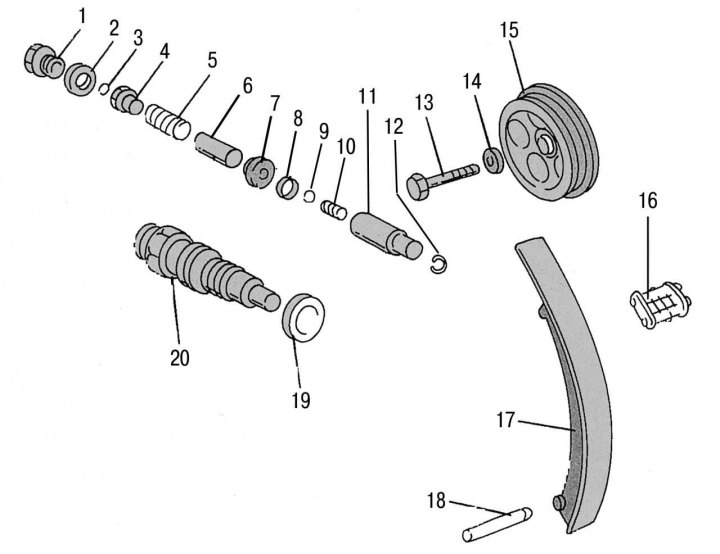
Figure 95 a. Timing chain tensioner mechanism: 1 - cork; 2 - plug gasket; 3 - ball; 4 — spring seat; 5 - pressure spring; 6 - finger; 7 - relief valve; 8 - sealing ring; 9 - ball; 10 - pressure spring; 11 — push rod; 12 — retaining ring; 13 — bolt securing the sprocket to the camshaft; 14 — washer of the bolt securing the sprocket to the camshaft; 15 — bolt securing the sprocket to the camshaft; 16 - chain lock; 17 - chain tensioning shoe; 18 - shoe support finger; 19 — sealing gasket of the chain tensioner on the cylinder head; 20 — chain tensioner
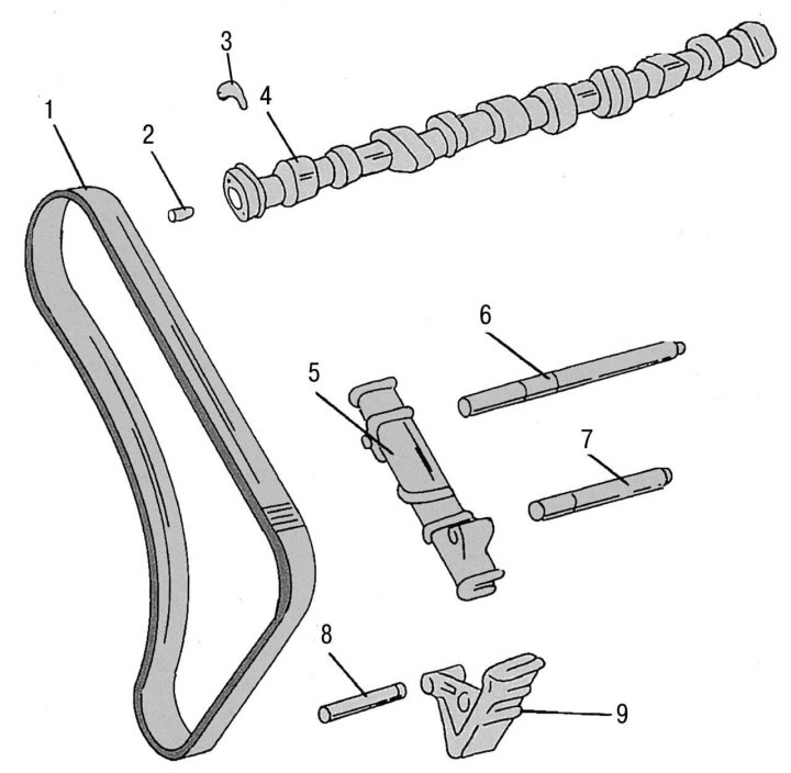
Figure 95 b. Other parts of the camshaft drive mechanism: 1 - double row drive chain; 2 - landing pin; 3 - camshaft thrust washer; 4 — camshaft; 5 - chain tensioner bars; 6 — support pin of the chain guide on the cylinder block; 7 — chain guide support pin; 8 — landing pin; 9 - chain guide groove
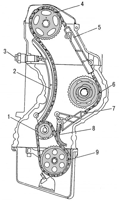
Figure 96. Camshaft drive mechanism assembly: 1 - crankshaft sprocket; 2 - chain tension shoe; 3 - chain tensioner; 4 — camshaft drive sprocket; 5 - chain tensioner; 6 — fuel pump drive sprocket; 7 - chain tensioner; 8 — oil pump drive chain tensioner lever; 9 — oil pump drive sprocket
All parts mentioned in this subsection can be replaced on the engine installed in the vehicle. The location of the camshaft drive chain and all associated parts is shown in the figure 95 a and 95 b. Figure 96 shows the assembled camshaft drive mechanism.
The camshaft drive chain drives the camshaft sprocket, the fuel pump sprocket, and is itself driven by the crankshaft sprocket. The chain is supported by two bars - dampers. The chain tension is adjusted using a hydraulic tensioner located in the engine crankcase and acting on the chain tension shoe made of light metal.
The camshaft drive sprocket is fixed to the shaft with a key and secured with an M8 bolt.
The second small chain is designed to drive the oil pump. This chain is driven by the second sprocket of the crankshaft (a twin sprocket is installed on the engine crankshaft) and is equipped with its own tensioning device.