
Cars BMW Cars Volkswagen Cars Chevrolet Cars Land Rover Cars Lada Cars Honda Cars Peugeot
English Русский
Български
Беларускі
Український
Српски
Hrvatski
Română
Polski
Slovenský
Magyar
Bookmark News and articles Sitemap Feedback Site search
MercedesMan.ru


A-Class C-Class E-Class G-Class M-Class S-Class Others
Sprinter (1995-2000, diesel) Vito 1 (1996-2003) Vito 2 (2003-2014, diesel) Vario 814D (1996-2003, diesel)
  • Main
  • Mercedes-Benz
  • Sprinter (1995-2000)
  • Power unit
  • Engine repair
  • Dismantling and installation of the camshaft drive chain

Dismantling and installation of the camshaft drive chain (Mercedes-Benz Sprinter 903)

0
The camshaft and fuel pump are driven by a double-row drive chain. The camshaft and fuel pump drive sprockets have twice as many teeth as the crankshaft drive sprocket. Two chain guides support the chain on one side, and a pressure shoe, which is constantly pressed by the hydraulic tensioner damper, constantly presses the chain on the other side. Replacing the camshaft drive chain on an existing engine requires some skill and experience to prevent the chain from falling off the sprocket.

To replace the camshaft drive chain on a vehicle's engine, you will need to have a hand grinder on hand. New camshaft drive chains are supplied with removable locking links provided for their installation. The camshaft chain must be replaced as follows:
  • remove all parts that impede access to the camshaft drive chain;
  • remove oil spray nozzles (although this will require additional work, the engine will be easier to turn over);
  • remove the cylinder head cover;
  • remove the chain tensioner (subsection 2.12.1);
  • cover the chain case with a piece of rag;
  • use a grinder to file down the riveted heads of the chain link pins. Do not break the chain yet;
  • attach the new camshaft drive chain to the old chain by removing the worn link from the old chain;
  • using a wrench with a replaceable socket head and a ratchet inserted into the crankshaft belt pulley mounting bolt, slowly turn the crankshaft in the working direction of its rotation;
  • during the slow rotation of the crankshaft, it is necessary to maintain the old drive chain in a taut position by the free end, while its other end, connected to the new chain, will lead the latter onto the sprockets. Make sure that the chain does not come out of engagement with the camshaft drive sprocket and the crankshaft sprocket;
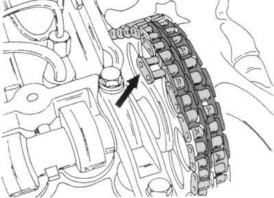
Figure 98. Installing the connecting link-lock in the drive chain (this operation must be carried…

Figure 98. Installing the connecting link-lock in the drive chain (this operation must be carried out from the side indicated by the arrow)


  • as soon as both ends of the new chain are at the top of the camshaft drive sprocket, the old chain is disconnected from the new one, and a removable locking link is inserted into the free holes of the rollers of the new chain from the inside out, as shown in the figure 98. Install new retaining rings on the chain connecting link pins. In this case, both ends of the chain should be temporarily tied with wire to the camshaft drive sprocket so that they do not fly off it into the chain housing;
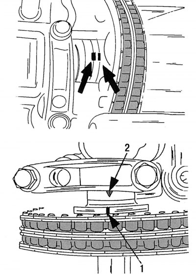
Figure 33. Location of the camshaft guide pin (top). Location of the timing marks corresponding to…

Figure 33. Location of the camshaft guide pin (top). Location of the timing marks corresponding to the position of the piston of the first cylinder at TDC (bottom): 1 - mark on the camshaft sprocket; 2 - mark on the cover of the first camshaft bearing

  • turn the crankshaft until the piston of the first cylinder stops at the TDC position. Then check (on the crankshaft pulley or on the vibration damper), so that in this position of the crankshaft pulley the camshaft marks take the position shown in the figure 33. If this does not happen, then it is necessary to check the camshaft and fuel pump drive mechanism, as described in the relevant subsections;
  • the remaining work is carried out in the reverse order of removal.

Note: Please note that drive chains can also be connected using conventional insert links. In this case, the outer plate of the chain must be pressed well against the rollers, and the protruding ends of the link pins must be riveted. This work should be done at a service station. The above description applies to chains with removable link locks.
This article is available at: russian, bulgarian, belarusian, ukrainian, serbian, croatian, romanian, polish, slovak, hungarian
The article has been verified: Levin Kirill Glebovich
Share with friends:
◀ Previous
Mercedes Sprinter / Engine repair
Next ▶

Removal and installation the camshaft drive chain tensioner
Camshaft Drive Mechanism — General Description
Front crankshaft oil seal
Rear crankshaft oil seal and its holder
Belt pulley and torsional vibration damper of the crankshaft
Removal and installation the chain tension shoe
Dismantling and installation of drive chain dampers
Removal and installation the crankshaft sprocket
Removal and installation the camshaft
Gas distribution mechanism
More similar articles for repairing other models

☛ Camshaft Position Sensor — Removal and Installation Mercedes W168 (1997-2004)
☛ Tensioner, sprockets and guides for the camshaft drive chain Mercedes 190 (W201) (1982-1993)
☛ Replacing the camshaft drive chain Mercedes W123 (1976-1985)
☛ Checking the condition of multi-rib belts for auxiliary drive units Mercedes W463 (1999-2019)
☛ Checking the condition of multi-rib belts for auxiliary drive units Mercedes W163 (1997-2005)
☛ Replacing the oil pump drive chain Mercedes W140 (1991-1998)
Link in different formats to this article
Comments and feedback from visitors
No comments yet


How much will 13 + 25 ?


Vario 814D (1996-2003, diesel) 
  • General information
  • Maintenance
  • Power unit
  • Engines 602.984/985
  • Engines 904.908/914/923/936
  • Transmission
  • Clutch
  • Manual gearbox 711.613
  • Manual gearbox 710.64/66
  • Manual gearbox 715.051
  • Automatic gearbox 723.345
  • Power take-off box
  • Chassis
  • Front suspension
  • Rear suspension
  • Steering
  • Brake system
  • Body and electrical equipment
  • Interior (internal elements)
  • Exterior (external elements)
  • Heater and air conditioner
  • Electrical diagrams
Vito 2 (2003-2014, diesel) 
  • General information
  • User manual
  • Maintenance
  • Diesel engine OM646
  • Engine repair
  • Cooling and lubrication system
  • Power and exhaust system
  • Transmission
  • Clutch
  • Car gearbox
  • Chassis
  • Front suspension
  • Rear suspension
  • Steering
  • Brake system
  • Body
  • Body elements
  • Electrical equipment
  • Equipment and devices
  • Security systems
  • Electrical circuits
Vito 1 (1996-2003) 
  • General information
  • User manual
  • Maintenance
  • Petrol engines 2.0 l
  • Engine repair
  • Lubrication system
  • Cooling system
  • Power and control system
  • Petrol engines 2.8 l
  • Engine repair
  • Lubrication system
  • Cooling system
  • Power and control system
  • Diesel engines 2.3 l
  • Engine repair
  • Cooling system
  • Lubrication system
  • Turbocharging and recycling
  • Power and control system
  • Diesel engines 2.2 l
  • Engine repair
  • Cooling system
  • Lubrication system
  • Turbocharging and recycling
  • Power and control system
  • Transmission
  • Clutch
  • Mechanical gearbox
  • Automatic gearbox
  • Chassis
  • Front suspension and wheels
  • Rear suspension
  • Steering
  • Brake system
  • Body
  • Exterior (external elements)
  • Interior (internal elements)
  • Electrical equipment
  • Equipment and devices
  • Heater and air conditioner
  • Electrical circuits
Sprinter (1995-2000, diesel) 
  • General information
  • Introduction to the guide
  • Maintenance
  • Power unit
  • Engine repair
  • Lubrication system
  • Cooling system
  • Power and exhaust system
  • Transmission
  • Clutch
  • Mechanical gearbox
  • Automatic gearbox
  • Front axle
  • Rear axle and cardan
  • Chassis
  • Car suspension
  • Steering
  • Brake system
  • Tires and wheels
  • Electrical equipment
  • Equipment and devices
  • Headlights and lighting
  • Power devices
  • Electrical circuits
 
MercedesMan.ru © 2017–2026 · Mobile version · Read about Mercedes · Sitemap: EN BG BY UA RS HR RO PL SK HU · Feedback · Site search · Bookmark A-Class (W168) · C-Class (W201) · C-Class (W202) · C-Class (W203) · E-Class (W123) · E-Class (W124) · E-Class (W210) · G-Class (W463) · M-Class (W163) · S-Class (W116, petrol) · S-Class (W126, petrol) · S-Class (W140) · S-Class (W220) · Sprinter · Vito 1 · Vito 2 · Vario 814D ·
 
We only use cookies without which some of the site's features may not be available.