
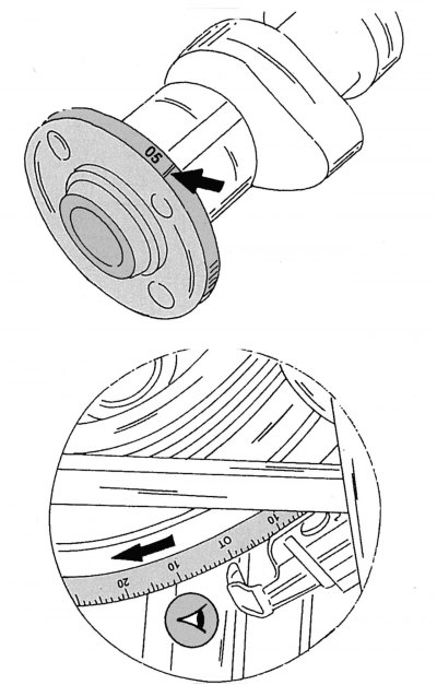
Pic. 108. Numeric identifier indicating the corresponding modification or size group of the camshaft (up). Correct direction of rotation of the crankshaft (at the bottom) to set the TDC position
Not all modifications of this engine have the same camshaft. The number stamped on the shaft, which is in the one shown in fig. 108 place, indicates its belonging to a particular type of engine. Camshafts of the so-called repair size groups (1st and 2nd repair dimensions) are also provided with a corresponding numerical identifier.
Only a camshaft with a specific identification number can be installed on your vehicle's engine. The camshaft is mounted on bearings in the cylinder head. The lower part of the bearings is cast in the form of nests in one piece with the cylinder head, to which the bearing caps are bolted.
The camshaft is removed after the bearing cap fasteners have been removed and its drive sprocket has been removed. The front end of the car is suitably disassembled to provide access to the components and parts necessary to perform the work. Removal and installation of the camshaft must be carried out in the following order:
- disconnect «mass» battery wire;
- remove the air intake pipe;
- remove the cylinder head cover. It is attached with 6 bolts on top of the engine;
- turn the engine shaft until the piston of the first cylinder stops at TDC, while «zero» the mark on the belt pulley should be set opposite the installation pointer. The engine shaft is rotated by the central bolt of the crankshaft pulley using a socket wrench with a ratchet;
Attention! Never attempt to turn the crankshaft by the camshaft sprocket center bolt with a wrench. The crankshaft must always be turned only in the working direction of its rotation. Having stopped the crankshaft in the desired position, pay attention to the position of the marks on the upper side of the camshaft, they should be opposite each other, as shown in Fig. 102.
- completely dismantle the chain tensioner (subsection 2.12.1);
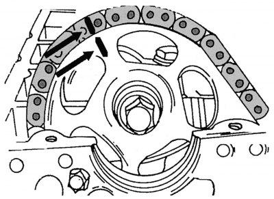
Pic. 99. Marks on the camshaft drive sprocket and drive chain
- on the camshaft sprocket and on its drive chain, it is necessary to apply marks with paint - two strips in one line, as shown by two arrows in fig. 99;
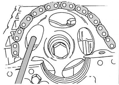
Pic. 100. Fixing the camshaft drive sprocket
- unscrew and remove the sprocket mounting bolt on the camshaft together with the washer. To prevent the camshaft from turning when the bolt is loosened between the spokes of the sprocket, it is necessary to insert a strong screwdriver or a thick bolt, as shown in Fig. 100. At the same time, you can attract an assistant who will fix the crankshaft from turning by the flywheel ring gear from below through the flywheel oil pan (torque converter);
- dismantle the sprocket from the camshaft, keeping the drive chain in a constantly taut position to prevent it from disengaging from the crankshaft sprocket;
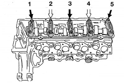
Pic. 109. The sequence of removing the mounting bolts of the bearing caps of the camshaft of a four-cylinder engine
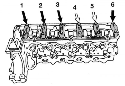
Pic. 110. The sequence of removing the mounting bolts of the bearing caps of the camshaft of a five-cylinder engine
- unscrew the bolts securing the camshaft bearing caps one by one in several steps and remove the bearing caps from the bearing racks in a certain order. On the four-cylinder engine it is necessary to adhere to the specified in fig. 109 unscrew and remove the bearing caps. First, the bolts securing the covers of the first, third and fifth bearings are unscrewed (bolts marked with black arrows), and then the bolts securing the covers of the second and fourth bearings are released alternately crosswise (marked with white arrows) until the force on the camshaft disappears. On a five-cylinder engine, the scheme for dismantling the mounting bolts and removing the bearing caps is shown in fig. 110. First, the bolts of the covers of the first, second, third and sixth bearings are unscrewed (black arrows), and then the bolts securing the covers of the fourth and fifth bearings are released alternately crosswise (white arrows) until the disappearance of the force on the camshaft;
- lift the camshaft from the bearings;
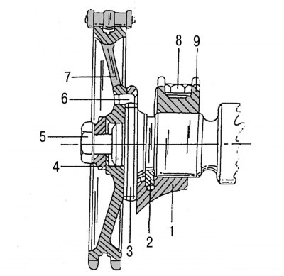
Pic. 111. Camshaft and its mounting in the cylinder head: 1 - cylinder head; 2 - persistent half ring; 3 - camshaft; 4 - washer; 5 - M10x50 mm bolt for fastening the camshaft drive sprocket; 6 - landing pin; 7 - camshaft drive sprocket; 8 - M8x45 mm bolt for fastening the camshaft bearing cover; 9 - camshaft bearing cover
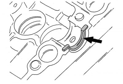
Pic. 112. Thrust half ring for axial fixation of the camshaft
- Pull the camshaft stop ring out of the groove in the cylinder head. On fig. 111 shows a section of the camshaft flange with a thrust half ring that limits the axial clearance of the camshaft. The landing groove of the half ring is shown in fig. 112.
- To check the valve lifters, they can be pulled out of the wells using a suction cup. After checking, install the pushers in their original places.
- When replacing the camshaft or cylinder head, the shaft should first be generously lubricated and, having installed it in the bearings, rotate it several times in order to identify possible jamming points. This work should be done in the following order:
- install the thrust half ring on the cylinder head, as shown in fig. 112. If the edges of the half-ring are worn out, then it must be replaced with a new one;
- lubricate the camshaft journals and lower it onto the bearing pedestals of the cylinder head. The pushers during this check must be removed from their seats;
- install the bearing caps in the appropriate sockets and tighten the fixing bolts with a torque of 25 Nm. Start tightening with the bolts of the middle bearings and gradually move towards the edges;
- screw the M10x30 mm bolt into the threaded hole for the sprocket mounting bolt, and then turn the camshaft using this bolt. If it seems that the shaft turns hard, then try to loosen the mounting bolts of individual bearings one by one while continuing to turn the camshaft. When you get to the bearing cap that caused the camshaft to rotate tight, the bearing cap must be removed and the operating clearance measured, taking into account the recommendations for crankshaft bearings. The clearance in the bearings should be between 0.050 and 0.081 mm. Otherwise, the cause of jamming may be a partial deformation of the camshaft (when installing a new camshaft, such a reason is excluded);
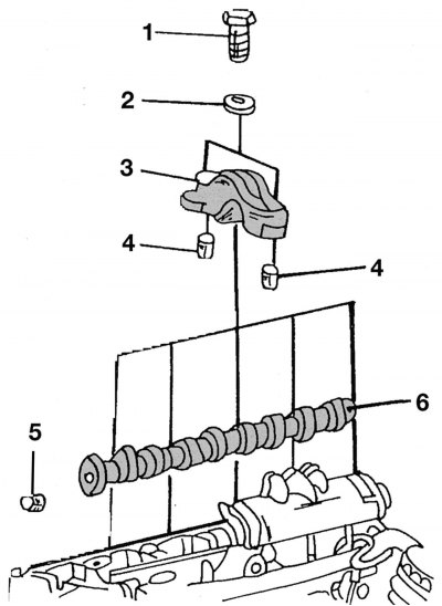
Pic. 113. Installing the camshaft: 1 — a bolt of fastening of a cover of the bearing, 23 Nm; 2 - washer; 3 — a cover of the bearing of a camshaft; 4 - landing sleeves; 5 - landing pin for the camshaft sprocket; 6 - camshaft
- dismantle the camshaft again. Its subsequent installation can be carried out using Fig. 113. This figure shows the camshaft of a four-cylinder engine;
- generously lubricate and install valve lifters in the appropriate landing wells;
- install the camshaft in the sockets and on the thrust half ring in the cylinder head;
- make a uniform, crosswise tightening of the fixing bolts of the covers of the second and fourth camshaft bearings of the four-cylinder engine with a torque of 25 Nm, as shown in fig. 109. After that, install the remaining bearing caps in the sockets and tighten their fixing bolts with the same torque;
- evenly crosswise, alternately tighten the fixing bolts of the caps of the second and fourth bearings of the camshaft of the five-cylinder engine to a torque of 25 Nm, as shown in fig. 110. After that, install the remaining bearing caps in the sockets and tighten their fixing bolts with the same torque;
- put the drive sprocket together with the drive chain on the camshaft, making sure that the marks previously applied with paint coincide, and the camshaft mounting pin enters the corresponding hole on the sprocket;
- Measure the length of the camshaft sprocket mounting bolt from the lower edge of the bolt head to the end of the threaded section. If the measurement result exceeds 53.6 mm, then a new bolt must be used. This bolt should be tightened with a torque of 25 N·m, after having previously fixed the sprocket from turning with the bolt (or a strong screwdriver), inserted into the hole between the sprocket spokes, as shown in fig. 100. After that, it is necessary to finally tighten this bolt by another 85–95°;
- mount the chain tensioner, tightening it with a torque of 80 Nm;
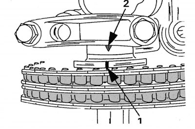
Pic. 102. The location of the marks when the piston of the first cylinder is at TDC
- check the timing marks of the camshaft for its correct installation in the position of the piston of the first cylinder located at TDC. The mark on the camshaft must be against the protruding mark on the cover of the first camshaft bearing when the piston of the first cylinder is set to TDC. These marks are clearly visible when looking at the camshaft from above, as shown in fig. 102;
- install the cylinder head cover in its place;
- do all other work in the reverse order to dismantling;
- start the engine and check for oil leaks.