



Contents: Removal ↡ Installation ↡
Removal
Note: New gaskets or a new seal will be required during installation (depending on what is used). A new oil feed tube O-ring may be required and a new front crankshaft oil seal is recommended.
1. Drain the engine oil and coolant as described in Chapter 1A.
2. Remove the air cleaner as described in Chapter 4.
3. Remove the radiator as described in Chapter 3.
4. Where applicable, remove the suspension leveling system hydraulic pump as described in Chapter 10. Note that the pump can be moved to the side without disconnecting the hydraulic pipes.
5. Remove the camshaft cover as described in paragraph 4.
6. Remove the water pump as described in chapter 3.
7. Remove the accessory drive belt as described in Chapter 1A.
8. On models with an automatic transmission, loosen the mounting bolts and remove the air conditioning compressor drive belt tensioner stand (see fig. 6.8).
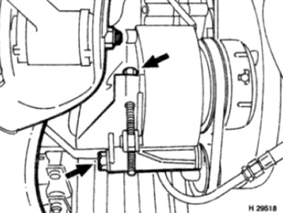
Fig. 6.8. Fastening bolts (shown by arrows) air conditioning compressor drive belt tensioner struts
9. On models equipped with air conditioning, remove the bolts and compressor bracket from the engine. Then, remove the bolts and move the compressor out of the work area without disconnecting the refrigerant line (see fig. 6.9). Make sure the compressor is securely supported and the tubes are not stretched.
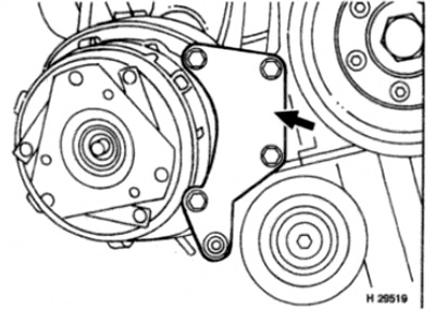
Fig. 6.9. Unscrew the bracket mounting bolts (shown by arrow) air conditioning compressors
Warning: Do not attempt to disconnect refrigerant pipes - refer to Chapter 3 for precautions to take when working on models equipped with air conditioning.
10. Turn the crankshaft so that piston No.1 is in the TDC position so that the crankshaft timing marks are positioned as described in paragraph 3.
11. Remove the crankshaft pulley/vibration damper and hub as described in paragraph 5.
12. Remove the ignition distributor as described in Chapter 5.
13. Where provided, remove the TDC sensor as described in Chapter 4.
14. Disconnect the throttle cable from the linkage and move it out of the work area as described in Chapter 4.
15. Where required, loosen the bolt and disconnect the gearbox ground bus from the body.
16. Remove the rear engine mount as described in paragraph 17.
17. Remove the oil pan as described in paragraph 12.
18. Unscrew the two bolts securing the oil pickup tube bracket to the main bearing cap, then unscrew the nut securing the tube to the bracket and remove the bracket.
19. Working inside the camshaft timing chain housing, from above the cylinder head, remove the three bolts securing the cylinder head to the timing chain housing (see fig. 6.19).
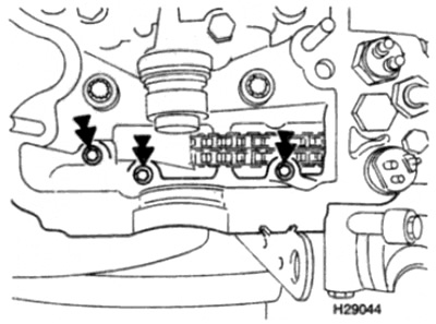
Fig. 6.19. Fastening bolts (shown by arrows) cylinder heads to camshaft timing chain housing
20. Unscrew the remaining bolts securing the chain cover to the cylinder block (remember the location of the bolts as they vary in length), then remove the casing from the keys and remove it together with the oil intake pipe (see fig. 6.20). Be careful not to damage the cylinder head gasket.
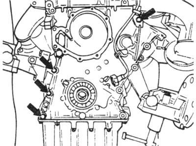
Fig. 6.20. Unscrew the remaining bolts (shown by arrows) drive chain cover fastenings
21. If not already done, remove the woodruff key from the crankshaft.
22. Move the bushing off the crankshaft. If the bushing is tight, carefully pry it off with a lever.
Installation
23. Carefully inspect the condition of the cylinder head gasket on the mating surface with the camshaft timing chain housing. If damage is detected, the gasket should be replaced (see paragraph 11).
24. Carefully remove all traces of old gasket or sealant from the mating surfaces. Note that the housing seal may be made with a gasket or sealant.
25. The front crankshaft seal located in the chain case must be replaced. Pry the seal out with a screwdriver, then position the new seal and drive it into the case using a hammer, a wooden block and the old seal (see Fig. 6.25, a-c).
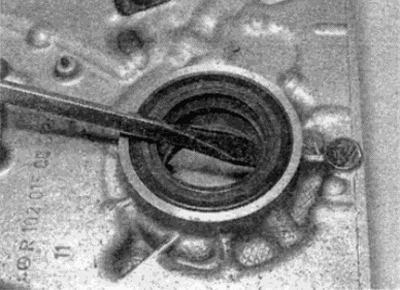
Fig. 6.25, a. Pry out the old crankshaft seal...
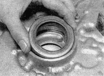
Fig. 6.25, b....and install a new cuff...
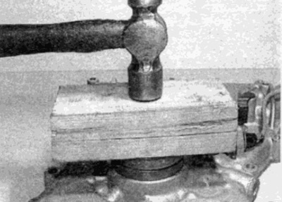
Fig. 6.25, c....and hammer it into the casing without skewing
26. Check the condition of the sealing ring of the oil feed pipe at the rear of the oil pump and replace if necessary. Lubricate the sealing ring with a small amount of grease (see fig. 6.26).
Material based on data from the portal [mercedesman.ru]
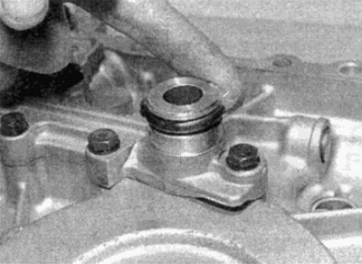
Fig. 6.26. Apply a layer of grease to the sealing ring of the oil feed pipe
27. Position a new gasket or apply a bead of sealant to the mating surface of the cylinder block (see fig. 6.27).
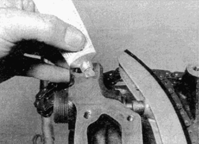
Fig. 6.27. Apply a layer of sealant to the surface of the cylinder block that meets the chain cover
Tip: If installing shims, apply a small amount of grease to help secure them to the surface.
28. Where required, trim the gasket in the areas shown in Figure 6.28 to remove excess sections. Note that the middle section on the top of the gasket must remain.
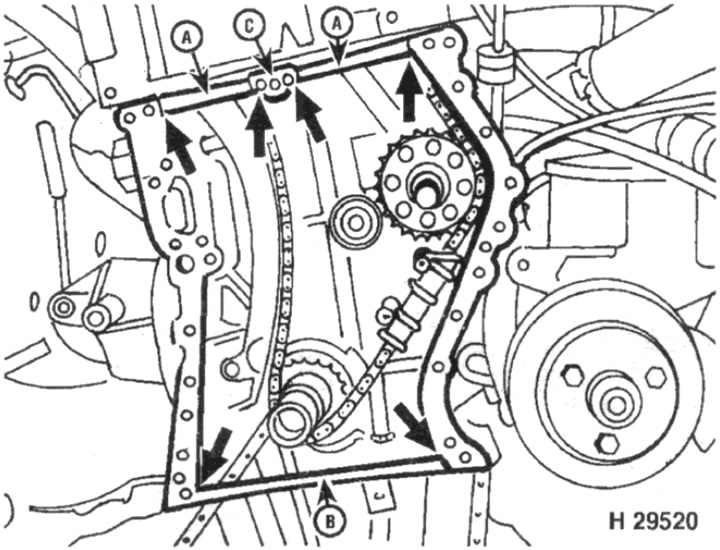
Fig. 6.28. Cut the gasket at the points shown to remove excess sections
A Upper Intersections
In the Lower Intersection
From the middle part
29. Place the chain cover on the mounting keys. If necessary, turn the inner rotor of the oil pump (located in the chain casing) so that the patches align with the slots in the oil pump sleeve on the crankshaft.
30. Install the chain case bolts that are not used to secure other components and tighten them by hand at this stage. Make sure that the bolts are installed in the same positions as before removal.
Note: When installing the parts in the following steps, do not overtighten the bolts that are also used to secure the chain cover.
31. Install the oil pickup tube bracket and tighten the mounting nut and bolts.
32. Carefully install the bushing into place at the front of the crankshaft. Be careful not to damage the crankshaft seal on the housing (see fig. 6.32). Install the woodruff key.
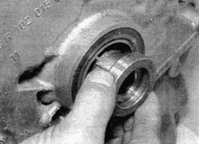
Fig. 6.32. Place the metal sleeve on the crankshaft
33. Where provided, install the compressor and air conditioner support bracket.
34. Install the three cylinder head to chain cover bolts, but do not tighten too much at this stage.
35. Gradually tighten all front chain case mounting bolts to the required torque. Tighten in a diagonal sequence (including bolts that fasten and other parts) - check that all bolts are tightened.
36. Install the tray as described in paragraph 12.
37. Install the rear engine mount as described in paragraph 17.
38. Where required, tighten the bolt securing the gearbox ground bus to the body.
39. Connect and, if necessary, adjust the throttle cable as described in Chapter 4.
40. Install the TDC sensor and adjust its position as described in Chapter 4.
41. Install the ignition distributor as described in Chapter 5.
42. Install the crankshaft pulley/vibration damper as described in paragraph 5.
43. Install and tension the accessory drive belt as described in Chapter 1A.
44. Install the water pump as described in Chapter 3.
45. Where provided, install the hydraulic pump for the suspension leveling system as described in Chapter 10.
46. Install the camshaft cover as described in paragraph 4.
47. Install the radiator as described in Chapter 3.
48. Install the air cleaner and connect the negative battery terminal.
49. Fill the cooling system and add oil to the engine as described in Chapter 1A.