
Removing
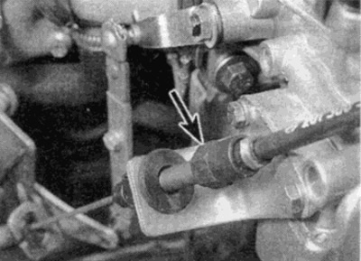
1. Working in the engine compartment, remove the square retainer (see fig. 7.1) and disconnect the throttle cable from the carburetor guide arm. Release the cable by passing it through the slot in the guide arm bracket.
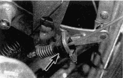
Pic. 7.1. Disconnect the throttle cable from the carburetor guide arm by removing the square clip (shown by arrow)
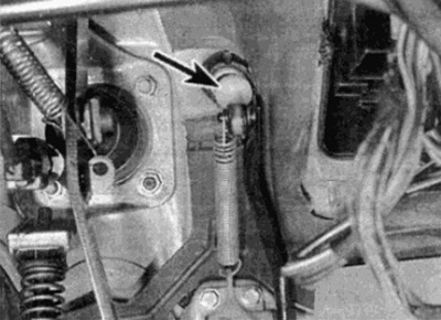
2. Remove the cable sheath from the bracket by depressing the tabs on the plastic retainer and removing it (see fig. 7.2).
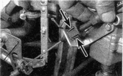
Pic. 7.2. Squeezing the paws (shown by arrows) plastic holder, remove the cable sheath from the bracket
3. Working in the driver's footwell, disengage the return spring, then remove the circlip and separate the cable from the top of the pedal arm.
4. Gently push the cable sheath through the engine bulkhead bushing.
Note: Do not remove the bushing from the baffle.
5. On the outer baffle, remove the rubber grommet, then pull the cable into the engine compartment through the bushing of the inner baffle.
Installation
6. Installing the cable is carried out in the reverse order of removal. Before connecting the cable to the carburetor linkage, adjust the linkage and cable as described in the next paragraph.
Adjustment
7. Start the engine and warm it up to normal operating temperature, then turn off the ignition.
8. Where fitted, disconnect the constant speed/air conditioner control link from the control lever on the carburetor.
9. On vehicles equipped with an automatic transmission, disconnect the end of the pressure control cable from the spherical socket on the guide lever.
10. On Stromberg Carburetor Models Equipped with Vacuum Throttle Follower Assembly (part of the toxicity control system), start the engine again and do the following:
- A) With the engine running, pinch the vacuum hose of the throttle valve pusher (with retracted throttle cam follower).
- b) Stop the engine.
- V) Check that the throttle lever is not touching the throttle cam adjusting screw.
- G) If necessary, turn the adjusting nut until the lever separates from the adjusting screw.
11. On Slromberg carburetor models, with the throttle cable disconnected from the guide arm, loosen the clamp screw on the linear linkage. Move the linkage until the roller rests against the idle speed limiter (see fig. 7.11). While holding the linkage in this position, tighten the clamp screw.
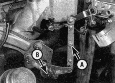
Pic. 7.11. Translational linkage device
A Tie-rod clamp screw
The roller
12. On models with a Pierburg carburetor, fully retract the throttle actuator pushrod by pinching the vacuum hose, start the engine for a few seconds, and turn the ignition off again. With the throttle cable disconnected from the guide arm, adjust the amount of control rod travel so that the travel is approximately 0.5 mm.
13. Connect the throttle cable to the guide arm.
14. On models with an adjustable full throttle stop behind the pedal, turn the throttle stop pin to the left and pull it out slightly.
15. Have an assistant depress the accelerator pedal fully on manual transmission models or just enough to approach (however, do not yet engage] the downshift switch on automatic transmission models.
16. At the same time, the throttle lever on the carburetor should touch the full throttle limit plate on the side of the carburetor. To achieve this, on models without a pedal stop, turn the adjusting nut on the damper mounting bracket (see fig. 7.16, a, b).
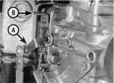
Pic. 7.16 a. The throttle lever on the carburetor must touch the full throttle limit plate
A throttle lever
B Full throttle limiter plate
Pic. 7.16b. Adjusting nut (shown by arrow) on support bracket
17. Release the accelerator pedal, allowing the roller to rest against the idle speed limiter on the guide arm. On models with an adjustable full throttle stop behind the pedal, lock the pin by turning it to the right. Be careful not to move your finger too far in or out.
18. In this position, the rod at the end of the throttle cable should rest against the compression spring without free play. To reach this position, adjust the adjusting nut on the cable on the pedal side - the adjusting nut can be unscrewed from the driver's seat (see fig. 7.18).
Pic. 7.18 Adjusting nut (shown by arrow) revolutions x.x. throttle cable to accelerator pedal
19. Where necessary, remove the clamp from the throttle actuator pusher vacuum hose.
20. If required, connect and adjust as described in Chapter 12, control rod for constant speed control / air conditioning.
21. On models with automatic transmission, connect the pressure control cable and adjust its operation as described in Chapter 7B.