
Front doors
Removal and installation
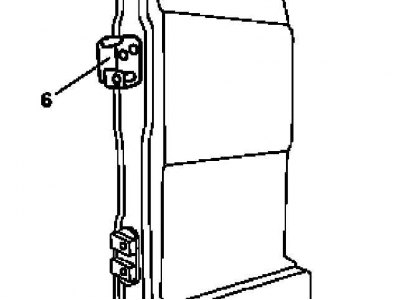
Door assembly
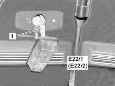
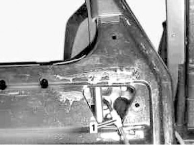
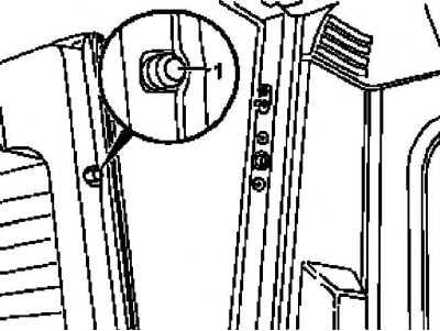
Connection details of the side turn signal repeater
1 - Wiring connector; E22 / 1 - Left side repeater; E22 / 2 - Right side repeater
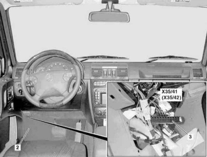
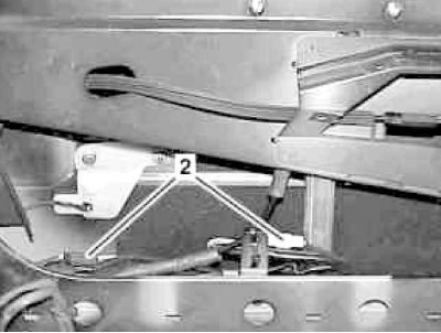
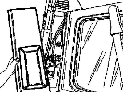
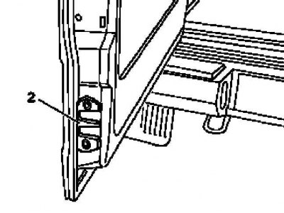
Driver's door wiring harness connector location
2 - Carpet; 3 - Connecting block for equalizing the ground potential; X35 / 41 - Driver's door wiring connector; Х35/42 - Passenger door wiring connector
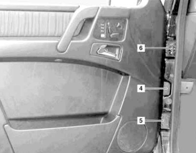
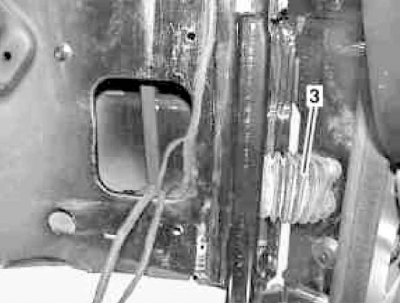
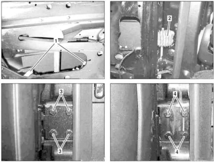
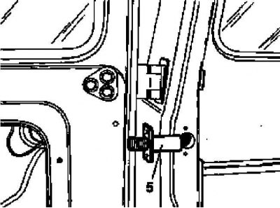
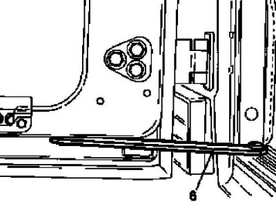
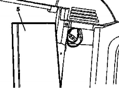
Door assembly installation details
4 - Rubber through sleeve; 5 - Lower loop; 6 - Upper loop
1. On models of the corresponding configuration (code ET2) activate the service mode of the TELE AID emergency call system (see Section Activation / deactivation of the service mode of the TELE AID emergency call system).
2. Turn on the auxiliary battery and connect it to the standard battery, then disconnect the negative cable from the latter.
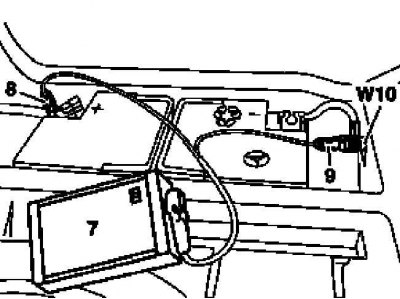
7 - Auxiliary battery
8 - Module positive wire terminal
9 - Terminal of the negative wire of the module
W10 - Battery Ground
3. Remove the corresponding side repeater turn signal (E22/1 or E22/2) and disconnect its electrical connector (1).
4. Remove the cover on the left or right (depending on which of the doors will be removed) under the dashboard (see Section Removal and installation of the lower covers of the panel of devices).
5. Peel off the carpet (2) from the A-pillar in the front footwell.
6. At the A-pillar in the appropriate footwell, disconnect the door wiring connector (X35/41 or X35/42).
7. Remove the appropriate contact elements from the earth potential equalization connection block (3).
8. At the A-pillar in the footwell, remove the ground wire from the side turn signal repeater.
9. Release the rubber lead-through sleeve (4) from the door assembly and from the A-pillar, - the damaged sleeve must be replaced.
10. Release the door wiring harness from pillar A - try to remember the route of laying the braid.
11. Support the door and remove the screws securing the bottom (5) and top (6) loops.
12. Remove the door.
13. Installation is in reverse order - do not forget to adjust the door (see below).
14. Appropriate models (code ET2) deactivate the service mode of the TELE AID system (see Section Activation / deactivation of the service mode of the TELE AID emergency call system).
15. Finally, read the DTCs and clear the OBD memory using the STAR DIAGNOSIS scanner (6511 1801 00) (see chapter Engine Electrical Systems).
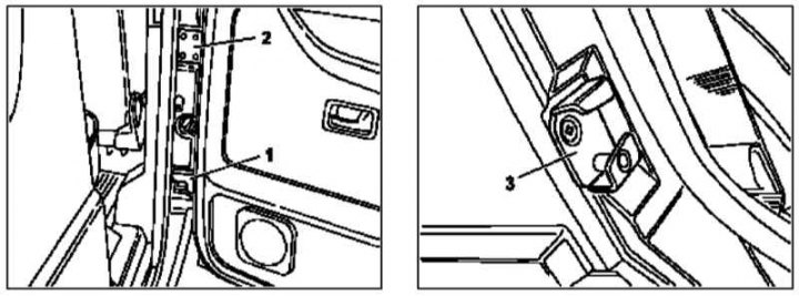
Door disassembled
Door mirror connection details
1 - Wiring connector
Location of internal connectors (2) door wiring
Rubber through sleeve (3) door wiring
1. Follow procedures 1 and 2 (see above).
2. Remove the panel of an internal upholstery of a door (see Section Removal and installation of an internal upholstery of door assemblies).
3. Disconnect the electrical wiring from the door speaker.
4. Remove the door control module (see chapter Onboard electrical equipment).
5. Carefully remove the film insulating coating of the door - in case of damage, the film must be replaced to prevent moisture from entering the passenger compartment.
6. Disconnect the connector (1) door mirror wiring.
7. Release from clips and disconnect connectors (2) door wiring - try to remember the route of laying the braid.
8. Release the rubber lead-through sleeve (3) from the door assembly and from the A-pillar, - the damaged sleeve must be replaced.
9. Release the wiring harness from the door assembly.
10. Support the door and remove the screws securing the bottom (5) and top (4) loops.
11. Remove the door.
12. Installation is in reverse order - do not forget to adjust the door (see below).
13. Appropriate models (code ET2) deactivate the service mode of the TELE AID system (see Section Activation / deactivation of the service mode of the TELE AID emergency call system).
14. Finally, read the DTCs and clear the OBD memory using the STAR DIAGNOSIS scanner (6511 1801 00) (see chapter Engine Electrical Systems).
Adjustment
Door assembly adjustment
1 - Lower loop; 2 - Upper loop; 3 - Locking wedge
1. Loosen the screws securing the bottom (1) and top (2) loops. Also loosen the locking wedge screws (3).
2. Correct the position of the door in the body opening, ensuring that the gap is the same around the entire perimeter, and the surface of the door in the closed position of the latter is flush with the surface of the surrounding body elements - if necessary, place shims under the hinges, or remove them.
3. Having achieved the desired result, tighten the hinge fastening screws (4 and 5) and locking wedge (3).
4. Lubricate the lock mechanism and make sure the door closes smoothly.
5. Finally, paint the screw heads.
Rear doors
Removal and installation
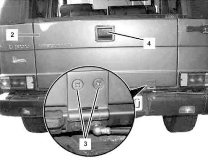
Tailgate Installation Details
1 - Wiring connectors; 2 - Rubber through sleeve; 3 - Bottom hinge screws; 4 - Top hinge screws
The procedure for performing the procedure is similar to that described above for the front doors, with the exception of the actions associated with disconnecting the wiring of the door mirrors and turn signal repeaters.
Adjustment
The procedure for adjusting the rear doors is completely the same as described above for the front.
Tailgate (station wagon models)
Removal and installation
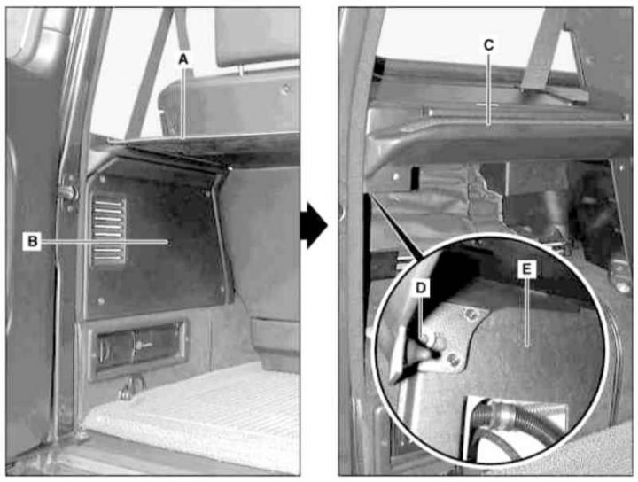
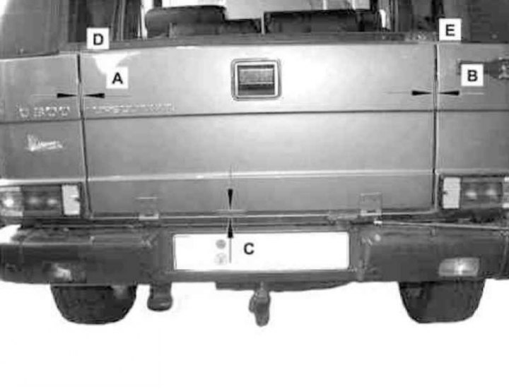
Tailgate installation details on Wagon models
A - Luggage cover; B - Cover of the side storage compartment; C - Stowage compartment; D - Fixing screw; E - Left C-pillar trim panel
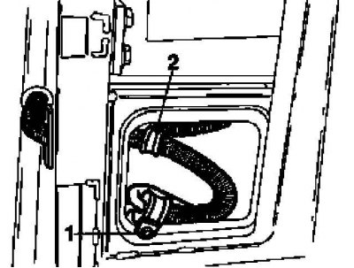
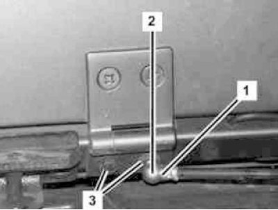
Tailgate Wiring Details on Wagon Models
1 - Retainer of the wiring harness; 2 - Return spring
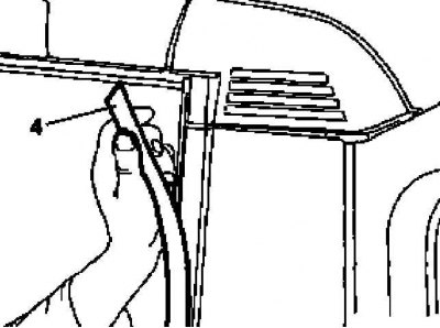
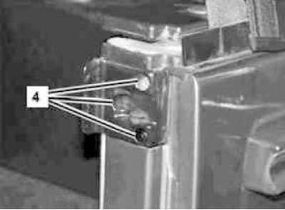
Removing the protector (4) the left edge of the tailgate opening on Wagon models
Removing the trim panel on the left rear pillar
Pass tube location (5) wiring and screws (7) fastenings of the upper hinge of the tailgate on Wagon models
Limiter location (6) opening and screws (8) fastenings of the bottom hinge of a door of a back on models the Station wagon
1. Follow the procedures in paragraphs 1 and 2 of subsection Front doors.
2. Remove the spare wheel.
3. Appropriate models (codes V53 and V57) remove the trunk lid (A).
4. Appropriate models (code V53) remove the cover (IN) side storage compartment, then remove the fixing screw (D) and separate the storage compartment (WITH) from the rear rack.
5. Remove the protector from the rear pillar (4) left side of the doorway.
6. Remove the panel (E) finishing of the left rear pillar.
7. Release the latch (1) door wiring harness.
8. Release the return spring (2).
9. Turn out fastening of fastening of a pass-through tube (5) wiring.
10. Remove the panel of an internal upholstery of a door (see Section Removal and installation of an internal upholstery of door assemblies).
11. Disconnect the rear wiper motor wiring connector - mark the wires, try to remember the route of the wiring harness.
12. Disconnect the wiring connector of the rear window heating element, - mark the wires, try to remember the route of the wiring harness.
13. Release the electrical wiring from the door assembly.
14. Release fasteners and disconnect from a door the limiter of the course of its opening (6).
15. While holding the door, unscrew the screws securing its top (7) and bottom (8) loops.
16. Remove the door.
17. Installation is in reverse order - do not forget to adjust the door (see below).
18. Appropriate models (code ET2) deactivate the service mode of the TELE AID system (see Section Activation / deactivation of the service mode of the TELE AID emergency call system).
19. Finally, read the DTCs and clear the OBD memory using the STAR DIAGNOSIS scanner (6511 1801 00) (see chapter Engine Electrical Systems).
Adjustment
Tailgate adjustment on Wagon models (1 of 5)
1 - Ball pin
Tailgate adjustment on Wagon models (2 out of 5)
2 - Drummer of the castle

Tailgate adjustment on Wagon models (3 out of 5)
3 - Latch
Tailgate adjustment on Wagon models (4 out of 5)
5 - Finishing panel
Tailgate adjustment on Wagon models (5 out of 5)
6 - Drummer of the castle
1. Remove the ball pin from the tailgate (1).
2. Remove the striker of the lock from the tailgate (2).
3. Remove the latch from the body element (3).
4. On models 463.246/250, follow the procedures in paragraphs 6 and 7 and remove the battery cover.
5. Remove the inner upholstery of the tailgate (see Section Removal and installation of an internal upholstery of door assemblies).
6. After releasing the fasteners, adjust the position of the door in the body opening in accordance with the same criteria as for the side doors (see paragraph 2). Also adjust the position of the striker (6) by tapping it with a hammer with the fastener released.
7. Install the components in the reverse order of their dismantling - do not forget to adjust the position of the striker accordingly (2) and latches (3).
Tailgate (Convertible models)
Removal and installation
Tailgate Installation Details on Convertible Models (1 of 3)
2 - Tailgate; 3 - Hinge screws
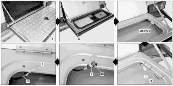
Tailgate Installation Details on Convertible Models (2 of 3)
5 - Cover panel; 6 - Tool compartment insert; 7 - Terminal activator of a single lock; 8 - Contact sensor-switch of the terminal; 9 - Connector contact sensor-switch; 10 - Plastic cap; 11 - Wiring; M14/7x1 - Single lock activator electric motor connector

Tailgate Installation Details on Convertible Models (3 of 3)
1 — Screw of fastening of the limiter
1. Turn the spare wheel carrier aside.
2. Open tailgate (2).
3. Open the lid (5), release the latches and remove the insert (6) tool compartment.
4. Disconnect the connector (М14/7x1) single lock activator electric motor.
5. Using steel wire or a narrow screwdriver, remove the terminals from the connector (7).
6. On the left in the tailgate frame, disconnect the terminal (8) from connector (9) contact sensor-switch, - again use a wire or a narrow screwdriver, after removing the plastic protective cap (10) and unlock the latch.
7. Release from board (2) both wiring harnesses (11).
8. Close the lid (5) tool compartment.
9. Remove the screws (1) fastenings of limiters of a course of opening of a board, - screws are subject to replacement without fail.
10. Close the side - try not to pinch the electrical wiring (11).
11. Remove the hinge screws (3), then open the board (2) and remove it from the car - use the help of an assistant.
12. Installation is carried out in the reverse order - in order to facilitate the refilling of the electrical wiring, lubricate the bushings with soapy water.
13. Finally, adjust the bead (see below)
Adjustment
Tailgate adjustment (1 of 3)
1 - Gas-filled holder of the spare wheel bracket; 2 - Ball head; 3 - Hinge bolts
Tailgate adjustment (2 of 3)
4 — Bolts of a locking wedge
Tailgate adjustment (3 of 3)
A, B, C - Clearances
D, E - The upper edge of the closed side must be flush with the rear body panels
1. Release the holder (1) spare wheel bracket and remove it from the ball head (2).
2. Loosen the hinge bolts (3).
3. Fold back the bead and loosen the locking wedge screws (4).
4. Tighten the bolts (3) And (4) so that it remains possible to adjust the position of the components they fix by tapping with a hammer.
5. Close the bead and make sure the gaps are the same (A, B and C) his landing in the body opening. Also make sure that the top edge of the bead (D and E) closes flush with surrounding body panels.
6. If necessary, correct the fit of the hinges and the locking wedge.
7. Finally, do not forget to tighten the mounting bolts.