



Removal
1. Disconnect the ground (–) cable from the battery terminal.
Attention! This will erase the radio's anti-theft code.
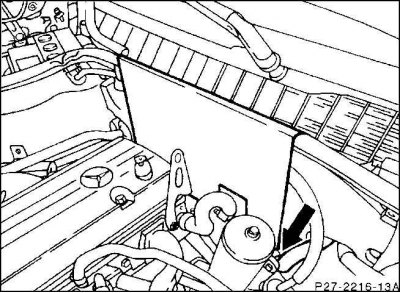
2. Cover the rear wall of the engine compartment with suitable sheet material to avoid damaging the insulating mat when lowering the gearbox.
Caution! For vehicles with an additional heating system, when lowering the gearbox, make sure that the coolant hose in the area of the rear wall of the engine compartment is not damaged (arrow).
3. Raise the car, support the gearbox with a special car jack (in the auto repair shop) and wooden spacers.
4. Remove the lower engine compartment protective cover.
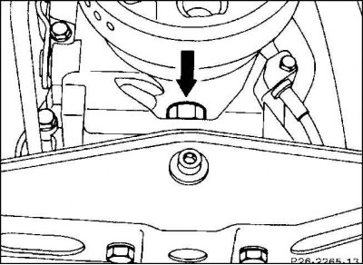
5. Remove the engine shaft bearing from the rear gearbox cover (arrow).
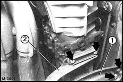
6. Unscrew the engine support bracket (1) from the body frame base (arrows).
7. Remove the exhaust system. Unscrew the holder (2) on the gearbox (arrow). Mark the position of the lining plate with a compass in advance (describe a circle), so that it can be reinstalled in its original place later.
8. Unscrew the screen to the intermediate bearing of the cardan shaft.
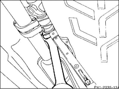
9. Loosen the clamp nut on the driveshaft.
10. Loosen, without unscrewing, the bolts to the intermediate bearing of the propeller shaft.
11. Unscrew the cardan shaft on the gearbox. At the same time, leave the joint disk on the cardan shaft.
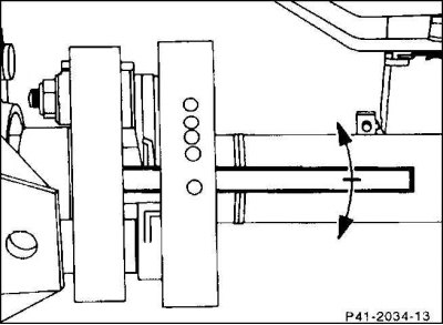
12. Loosen the relief bushings in the hinge flange using a cylindrical rod with a diameter of 10 mm and a length of about 150 mm.
13. Press the driveshaft back as far as the intermediate bearing and clamping piece will allow.
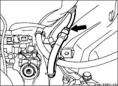
14. Disconnect the line going to the distributor cylinder on the left side of the hose connection (arrow). Collect the leaked brake fluid. Close the joints with plugs.
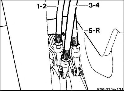
15. Remove the shift fork rods from the intermediate levers on the shift mechanism bracket, after first pressing the safety clips.
16. Remove the bolts from the starter flange.
17. Remove all mounting bolts from the gearbox on the intermediate flange, removing the top three bolts last.
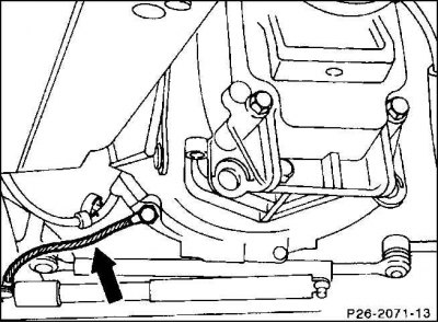
18. Unscrew the wire connecting the battery to the vehicle ground.
19. Turn the gearbox to the left, remove it horizontally backwards and remove it from the clutch.
20. Lower the gearbox.
Caution! Lower the gearbox only after the input shaft has been carefully removed from the clutch disc, otherwise the clutch disc may be damaged.
Installation
1. Check the coupling before installation.
2. Check the ease of movement of the clutch release bearing. Lubricate the bearing, for example, with grease "Liqui Moly V-320". If, before disassembling, noise was heard in the operation of the clutch release bearing when the clutch was engaged, replace the bearing.
3. Clean and lightly lubricate the input shaft V-gear and centering pins with molybdenum paste or molybdenum spray lubricant.
Please note! The clutch disc hub ring gear for the twin-housing flywheel is nickel-plated. Therefore, for 2.2/2.8 liter engines, there is no need to lubricate the gear ring gear of the primary shaft of the gearbox.
4. Shift into first gear.
5. Lift, turn to the left and horizontally insert the gearbox into the clutch. If the input shaft of the gearbox does not lock into the clutch disc when inserted, manually turn the input shaft from behind in the flange for the cardan shaft.
6. Screw the gearbox to the intermediate flange, while screwing the battery ground wire to the gearbox on the bottom left.
Tightening torque:
- Bolt M 10 x 40 - 55 Nm.
- Bolt M 10 x 45 - 55 Nm.
- Bolt M 10 x 90 - 45 Nm.
7. Tighten the starter firmly with two bolts.
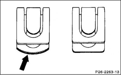
8. Hang the shift fork rods on the intermediate levers and secure them with the safety clips. At the same time, compress the spring clamps, push the slot into the groove of the shift fork rod and secure it there.
Caution! Use only safety clips with curves (arrow). When assembling, the clips must engage to ensure secure support.
9. Connect the pipe to the distribution cylinder.
10. Pull the cardan shaft out of the sliding part as far as possible and flange it to the gearbox. To do this, slightly raise the engine and gearbox using a garage jack and wooden spacers.
11. Securely bolt the rear engine mount with bracket to the gearbox.
12. Securely bolt the engine mount bracket to the body base frame.
13. Screw the intermediate bearing of the cardan shaft firmly.
14. Tighten the clamping nut firmly to a torque of 35 Nm.
15. Tightly screw the shield for the intermediate bearing of the cardan shaft.
16. Install the exhaust system, checking the rubber rings for porosity and damage.
17. Bleed the clutch control drive.
18. Check the gear shift setting.
19. Install the lower engine compartment cover.
20. Lower the car.
21. Remove the sheet material from the engine compartment.
22. Connect the ground (–) wire to the battery terminal.
23. Set the time on the clock.
24. Enter the radio anti-theft code.
Adjustment
Gear shift system
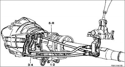
1-2. First and second gear shift fork rod
3-4. Third and fourth gear shift fork rod
5-R. Fifth gear and reverse gear shift fork rod
1. Set the gearbox to idle position (neutral position).
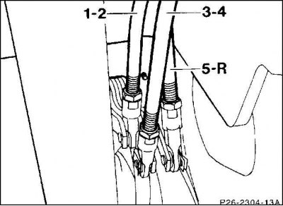
2. Remove the safety clips, then unhook the shift fork rods on the intermediate levers.
- 1-2 = intermediate lever for first and second gear;
- 3-4 = intermediate lever for third and fourth gear;
- 5-R = intermediate lever for fifth gear and reverse gear.
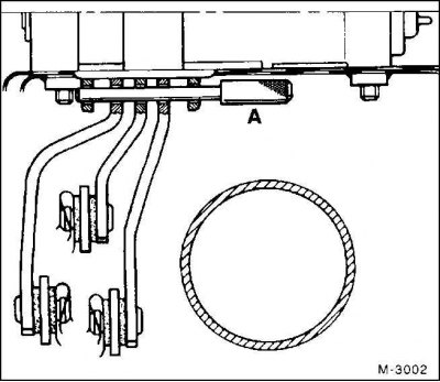
3. Insert the locking bolt (A) into the holes at the bottom of the gearshift bracket to secure the three intermediate levers.
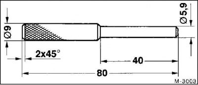
4. If required, fabricate a retaining bolt to the specified dimensions.
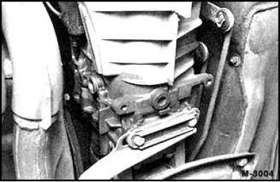
5. The shift fork rods should be pressed onto the intermediate lever bolt without tension. If not, loosen the lock nut and set the shift fork shield to the appropriate length. Tighten the lock nut firmly.
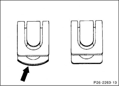
6. Secure the gear shift fork rods (1) with safety clips.
Caution! Only safety clips with roundings (arrow) may be used.
(Material based on data from the portal MercedesMAN.ru)
7. Remove the retaining bolt.
8. Check the operation of the gear shift system with the engine running. The gears should be engaged without sticking.