
Removing
1. Before starting work, check that the engine is completely cool. Disconnect the negative battery terminal.
2. Refer to paragraph 2 and remove the air cleaner.
3. With appropriate clamps (no vise), clamp the fuel supply and drain hoses from the carburetor, then loosen the clamps and remove the hoses from the carburetor. Get ready for some gasoline to spill - place a container under the hoses and cover the surrounding surfaces with rags.
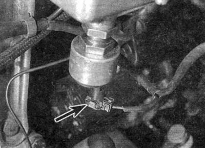
4. Briefly loosen the expansion tank cap to relieve pressure in the cooling system. Clamp the coolant hose to the air damper body with an appropriate clamp (don't use a vise). Then loosen the clamps and disconnect the hoses from the carburetor (see fig. 10.4). Be prepared to spill coolant by placing a container under the hoses and covering the surrounding area with rags.
Note: If you do not have the correct hose clamps, please contact Chapter 1A and before disconnecting the hoses, partially drain the coolant.
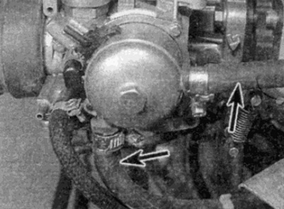
Pic. 10.4. Disconnect cooling hoses (shown by arrows) from the carburetor - Stromberg carburetor
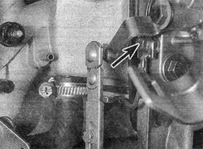
5. As described in paragraph 7, disconnect the throttle cable from the carburetor. It is possible to disconnect the throttle linkage from the throttle lever (see fig. 10.5).
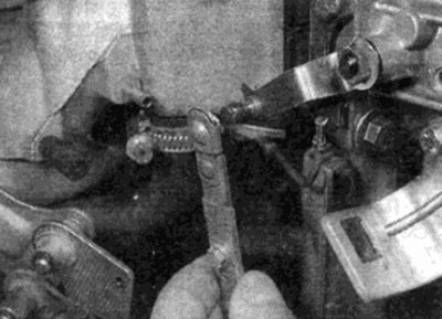
Pic. 10.5. Disconnecting Throttle Lever Link - Stromberg Carburetor
6. Where necessary, disconnect the constant speed control/air conditioning control link from the control lever on the carburetor.
7. On vehicles with automatic transmission, where provided, as described in Chapter 7 Part B, disconnect the pressure control cable from the carburetor.
8. Disconnect the connectors of all wires coming from the carburetor, marking them well so that they can be reinstalled correctly. Additionally, unscrew the bolt and disconnect the ground wire from the carburetor (see fig. 10.8, a-g).
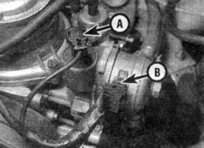
Pic. 10.8, a. Disconnect the wire connectors from the solenoid outlet valve (A), damper housing (IN)...
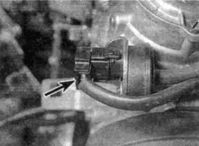
Pic. 10.8, b.... thermo-valve with delay (shown by arrow)
Pic. 10.8, c....and a fuel shut-off valve (shown by arrow)
Pic. 10.8, d. Earth wire fixing bolt (shown by arrow)
9. Write down the connection points to the carburetor of each vacuum hose, then disconnect them.
10. Turn away bolts and remove a rack of fastening of an inlet collector (where it is installed). Loosen and remove the bolts securing the carburetor to the intake manifold. Remove spacer and gasket.
Installation
11. Installation of the carburetor is carried out in the reverse order. Consider the following points:
- A) Do not use old gaskets, always install new ones.
- b) Screws of fastening of a spacer tighten with the demanded moment.
- V) Install the inlet and return petrol hoses in accordance with the arrows marked on the carburetor.
- G) Connect all connectors and vacuum hoses, in accordance with the designations made during removal.
- d) Connect the cooling hoses to the air damper body and add fluid to the cooling system to the required level
- e) Where provided, connect a constant speed control/air conditioner link to the carburetor (see chapter 12).
- and) On vehicles with automatic transmission, connect the pressure control cable to the carburetor (see Chapter 7 B).
- h) Check the level and if necessary. add oil to the carburetor damper. as described in Chapter 1A
- And) At the end, check the speed x.x., increased speed xx. and CO content in exhaust gases see chapter 1A)